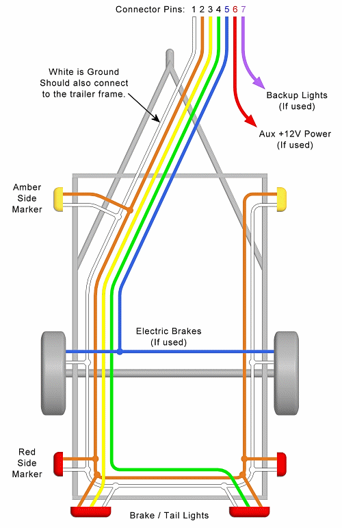
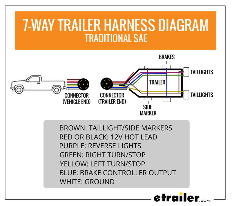
This is the general configuration upon which 5 way 6 way and 7 way wiring systems build upon. The possible causes are.
Led Marker Turn Signal Brake Light Wiring Diagram Brake
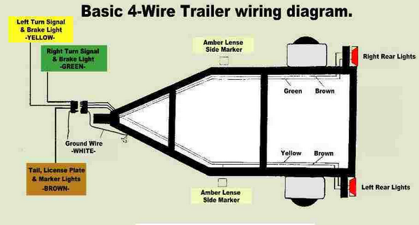
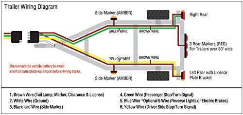
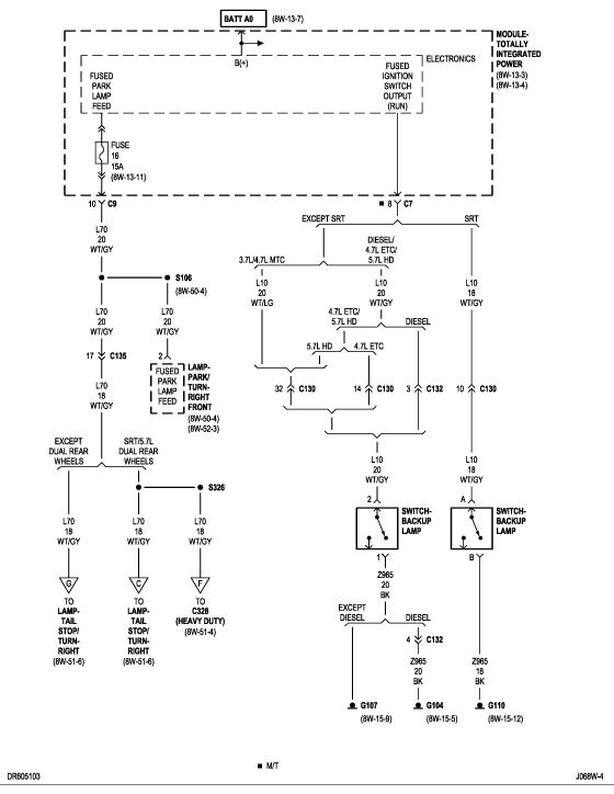
Side marker light wiring diagram. It will not come on when the park lights are engaged. Please see the trailer wiring diagram and connector application chart below. As an example you will find another blue wire in a 5 way system that powers auxiliaries like the electric brakes. On a vehicle this will be the wire supplying the parking lights or rear tail lights. The 4 pin connector only has the first 4 items listed. Converter shorting out when too many amps are drawn through the converter box it can be shorted out.
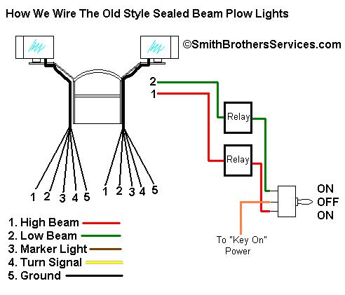
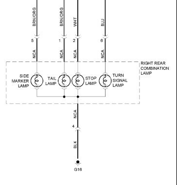
Wiring marker lights to either your vehicle or trailer is not complicated and can be performed with a minimum of tools and expertise. This is how you wire the side marker to function as a park light and signal lighthazard light. The left brake wire and left turn signal are yellow. Each incandescent taillight draws about 2 amps and side marker lights typically draw about 05. In the third diagram. White remains as the ground.
Yellow left turn signal left brake light 4. Too many lights on the trailer. Make sure to correct any trailer wiring problems before installing a new wiring harness. Side marker lights are powered by the brown wire. The rest you can ignore. Marker lights must be visible from each side of the vehicle.
Green right turn signal right brake light. Identify the appropriate power wire for marker lights. This is how you wire the side marker to function only as a turn signalhazard light. The black wire will be the power wire and the white wire is the ground wire. Brown tail lights side markers and running lights see brown wire notes below 3. In the second diagram.
When installing a sidemarker light such as this optronics trailer light mcl44ab you will want to splice into the signal wire for your trailer running lights circuit and then run the ground wire to a clean metal surface.
Gallery of Side Marker Light Wiring Diagram