Shunt trip breaker wiring diagram which related with safety and protection of electricity. Square d shunt trip breaker wiring diagram.

Yg 6400 Shunt Trip Breaker Wiring Diagram On Alert Circuit
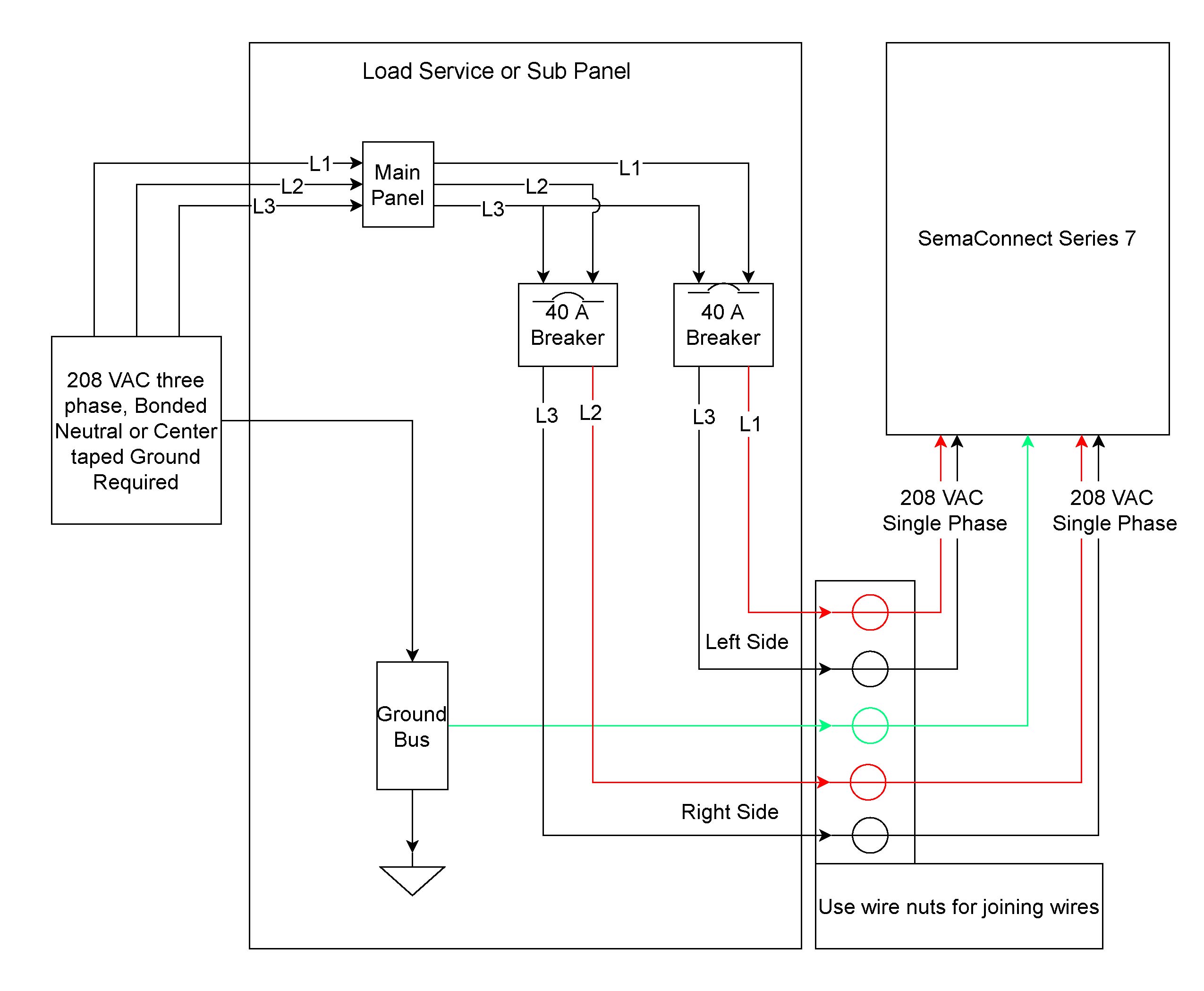
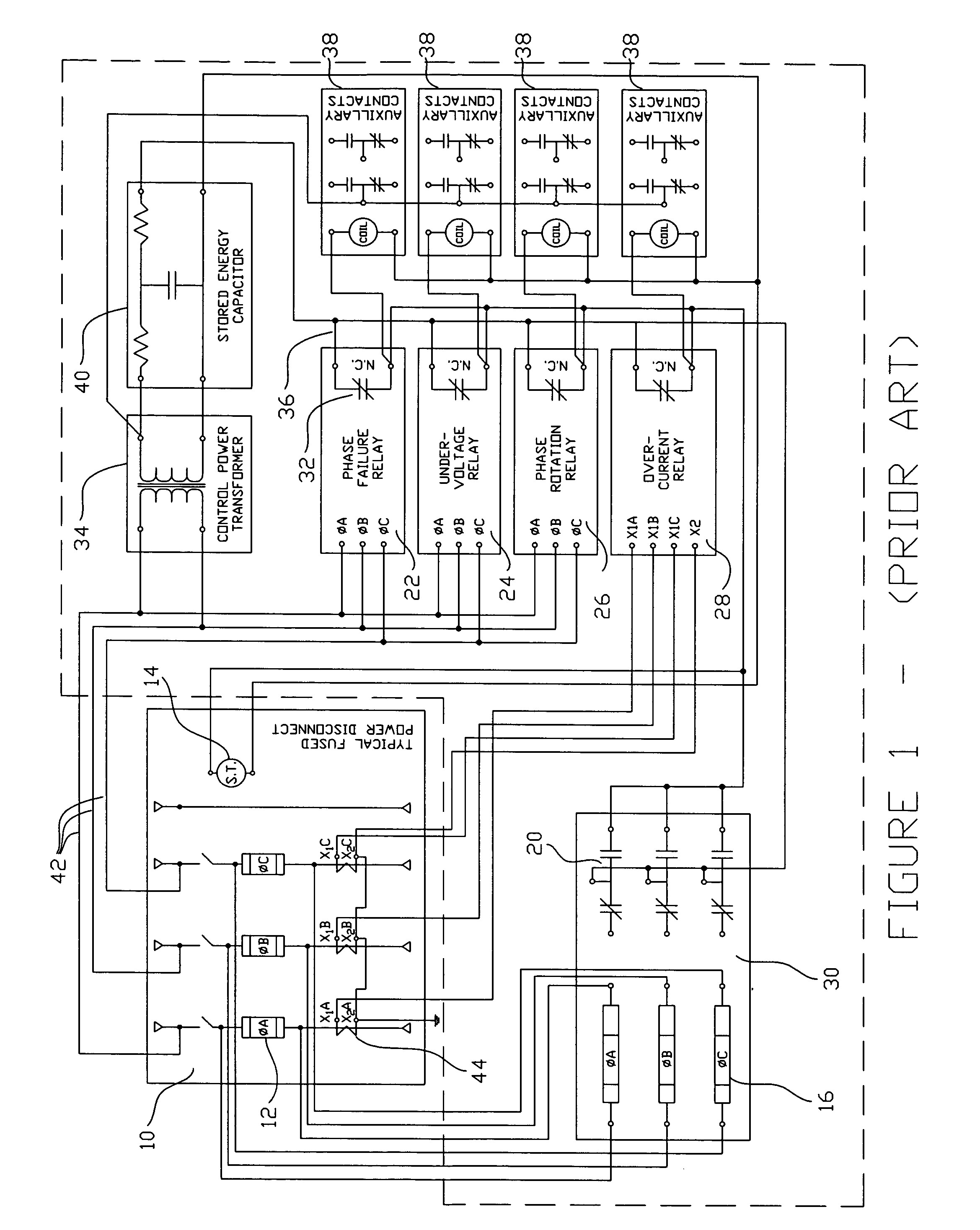
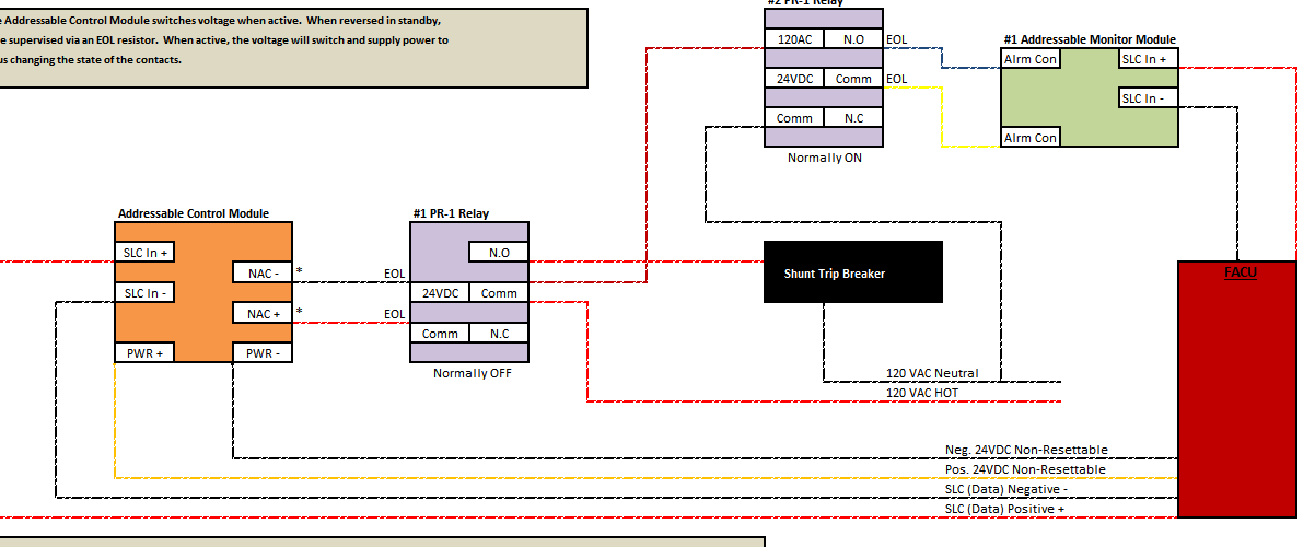
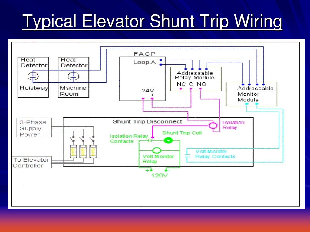
Shunt trip breaker wiring diagram. As you know that electricity is dangerous but its become more dangerous when its upgrade from the 220 volts to 3 phase 440 volts. It shows the parts of the circuit as simplified forms and also the power and also signal connections between the tools. It reveals the components of the circuit as simplified forms and the power and also signal links in between the tools. Shunt trip circuit breakers are usually rated three phase 480v or higher and are installed in the same way as other three phase circuit breakers with extra remote control circuits to operate the shunt trip and indicate remotely whether the shunt trip circuit breaker has actually opened. Siemens shunt trip breaker wiring diagram shunt trip circuit breaker wiring diagram saleexpert me in square best ideas d and. Land the switch leg from the source contact on one terminal either and the neutral wire l2 x2 to the other terminal.
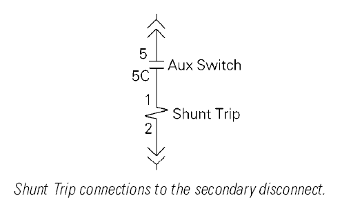
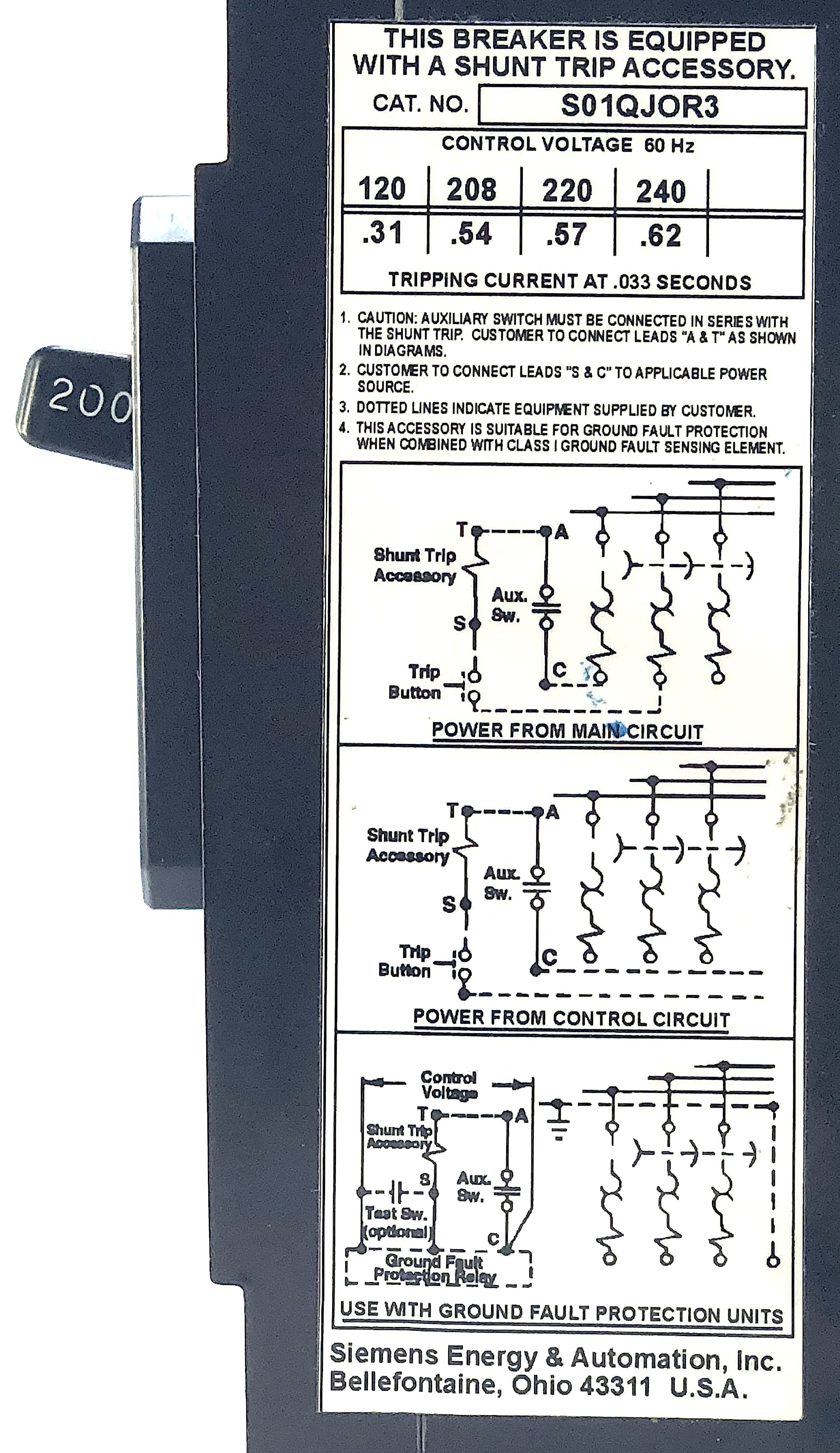
A wiring diagram is a simplified traditional photographic depiction of an electric circuit. Shunt trip st the shunt trip opens the circuit breaker when its coil is energized by a voltage input see table 1. The shunt breaker is 3 pole. Connect the appropriate voltage ie. Contactor wiring diagram for 3 phase motor. Electrical distribution equipment resolution.
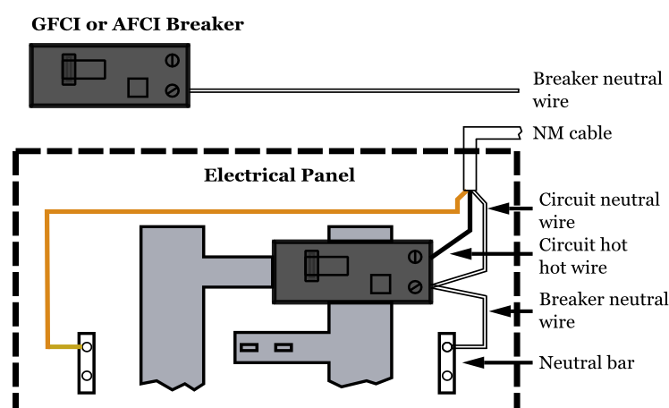
And line wire is controlled with kill switch. Also the symbol diagram is shown. Based on the information we took from google adwords square d shunt trip breaker wiring diagram has very much search online web engine. Shunt trip breaker wiring diagram for ansul system you almost certainly already know that square d shunt trip breaker wiring diagram has become the hottest topics over the internet today. The neutral wire is connected to the shunt coil. Collection of shunt trip wiring diagram square d.
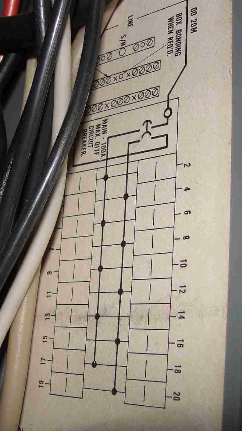
A wiring diagram is a simplified standard photographic depiction of an electric circuit. In the above mccb shunt trip breaker wiring diagram. The kill switch normally open contacts are used. 120v to 240v for the 1021 suffix to the two terminals on the shunt trip. The incoming 3 phase 4 wire system supply shown. September 11 2019 by larry a.
It is supplied with yellow and white secondary leads connected to a secondary connector plug see figure 2. Collection of square d shunt trip breaker wiring diagram. So neutral is required also. Which is used for 3 phase system. Circuit breakers qo environment. But the coil of shunt is 220 vac.
Gallery of Shunt Trip Breaker Wiring Diagram