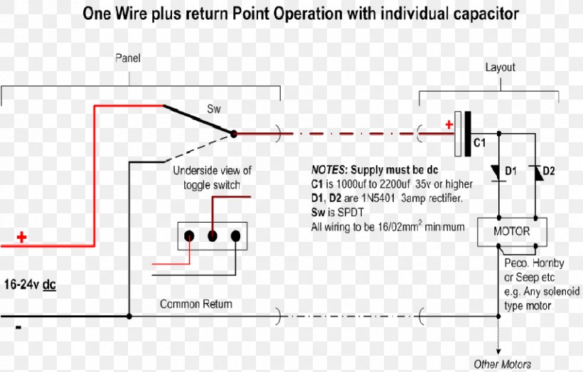
The are about 80 points so i need to get it right i have some peco motors to try and recently bought a couple of seep motors. I wonder if one of you kind experts would cast an eye over my diagram just to confirm i have got the right idea about wiring my seep pm1 points motors via a cdu correctly.

Point Motors Part 1 Solenoid Basics
Seep point motors wiring diagram. Seep motor point wiring for dc electrics dc getting you started. Today i built a test rig and wired up the seep motor to a peco streamline code 100 point. Especially with the aforementioned reference diagrams. As mre reader andy richardson explained in this profile of his layout they make a tremendous difference to the enjoyment of operating a layout. But as anyone who has ever tried fitting them knows installation is often problematic. Peco pl 13 accessory switches fit directly onto hornby point motors without modification and can be used for frog switching on live frog points such as peco electrofrogs points operated signalling to provide feedback for automatic control or just to indicate on a control panel that the point has.
Michael campbell details his approach. Wiring up a seep point motor duration. How to fit seep point motors. The solenoid is connected to a set of outputs on the ls150 and the switch to the dcc power bus and the point frog. Your model railway club. Fri jul 27th 2018 0931 pm.
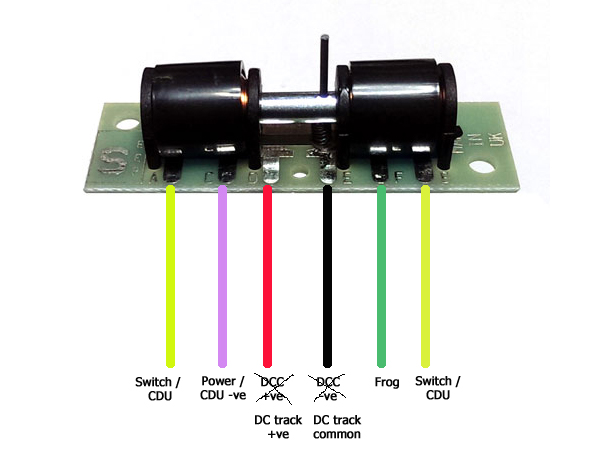
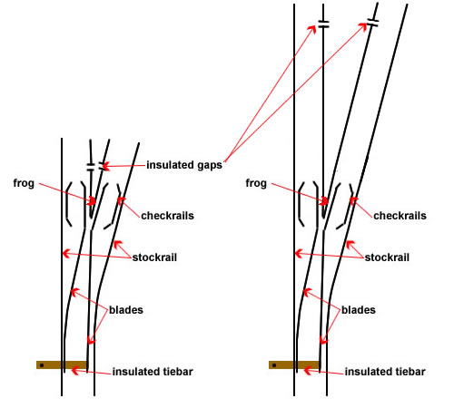
A quick look at how i wire my seep pm1 point motors. I know there are plenty of tutorials i just want the reassurance that i have understood them correctly before i damage anything. All droppers and point wiring is 1602 and the main power blocks x7 on this module and common feed are 2402. Wiring point work special track conditions for dc or dcc a reminder all examples and the things we use for switching such as cobalt motors cobalt s levers and ad or ad s accessory decoders will work as well on dc as they do on dcc so you can use these diagrams for any layout with any form of control. Wiring the seep pm1 is quite straightforward. Jammy dodger 6658 views.
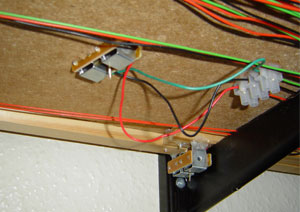
Basic point wiring diagram with hornby r044 passing contact switch. The picture below shows both motors in place along with the ls150 and the feed to the turnout frog ready to be attached to the polarity switch in the seep pm1. A quick look at how i wire my seep pm1 point motors. Motor operated points make a huge difference to layouts. It switches ok but i am getting an annoying buzz on each throw which i dont get when the motor is tested free of the point.
Gallery of Seep Point Motors Wiring Diagram


.gif)


.gif)