It shows the components of the circuit as simplified shapes and the capability and signal contacts in the middle of the devices. Wiring of rts451 consult the appropriate detector installation instructions for the applicable wiring diagram.
Ductsd Innovairflex
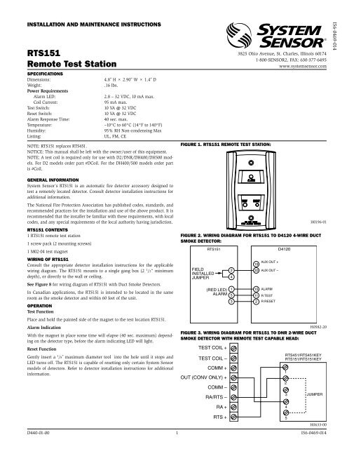
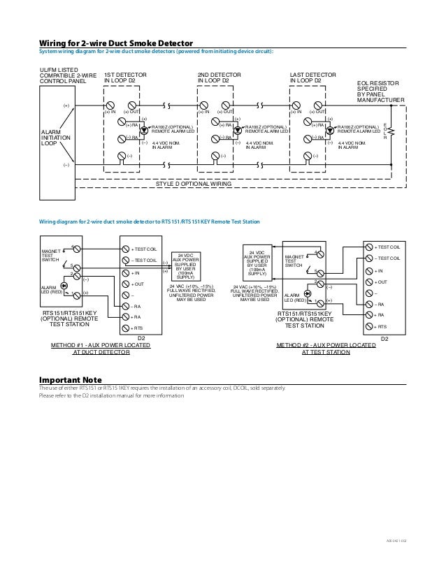
Rts451key wiring diagram. Wiring diagram for dh100acdclp to apa451. Dh100acdclp rts451rts451key 5 4 3 for rts451key only without a control panel. 19 20 15 2 6 1 5 4 3 rts451keya d4120 green led power red led alarm field installed jumper 11 2 aux out aux out alarm r test r reset 14 3 sup no supc sup. Page 2 reset reset ra test v out no connection h0156 00 h0194 01 figure 4. Power reset test red led alarm green led power dh100acdclp rts451rts451key 5 4 3. Wiring diagram for rts151 to dnr 2 wire duct smoke detector with remote test capable head.
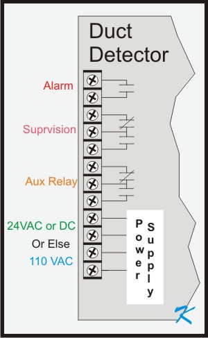
Contacts cannot be used if they are wired to control panel. 46 h 275 w 15 d. Wiring diagram for. Capability with the rts451rts151 or rts451keyrts151key remote test stations. Rts451rts451key rts151rts151key jumper 4 5 3 2 1 test coil test coil comm out conv only comm rarts ra rts h0633 00 figure 3. 24v 120 a c 220240 ac 9 10 a c ailable power inputs alarm auxiliar contacts for fan shutdown etc.
Wiring diagram for rts451key to dh400acdc duct smoke detector. 21 detector feature set utilizes plug in head part number sk photor sampling tubes install from front and rear compatible with existing accessories able to address detector per code switches on sensor head. 16 17 7 18 8 nc. Contacts transfer during alarm as. Power reset test red led alarm green led power field installed jumper 12 1 12 1 interconnect unit 1 interconnect dh100acdclp dh100acdclp unit 2 rts451rts451key 5 4 3 interconnect interconnect note. Wiring diagram for the rts451rts451key and interconnect feature 15 19 14 3 20 2 11 2 6 alarm signal 1 aux.
The rts451 mounts to a single gang box 21 2 minimum depth or directly to the wall or ceiling. Wiring instructions consult the appropriate detector installation instructions for the applicable wiring diagram. Power for rts451key only without a sup. Wiring diagram for rts151keya to d4120 4 wire duct smoke detector. The rts151key mounts to a single gang box 2 12 minimum depth or directly to the wall or ceiling. For the applicable wiring diagram.
Dh400acdc rts451key red led alarm alarm signal aux. Rts451key wiring diagram wiring diagram is a simplified standard pictorial representation of an electrical circuit. 3 contents of the duct smoke. The rts451key mounts to a single gang box 21 2 minimum depth or directly to the wall or ceiling. In canadian applications the rts151key is intended to be located in the same room as the smoke detector and within 60 feet of. In canadian applications the rts451keya is intended to be located in the same room as the smoke detector and within 60 feet of the unit.
15 19 14 3 20 2 11 2 6 alarm signal 1 aux. Alarm auxiliar contacts shown in standby. For 4 wire detectors the rts451key fea tures a multi colored led that alternates between steady.
Gallery of Rts451key Wiring Diagram