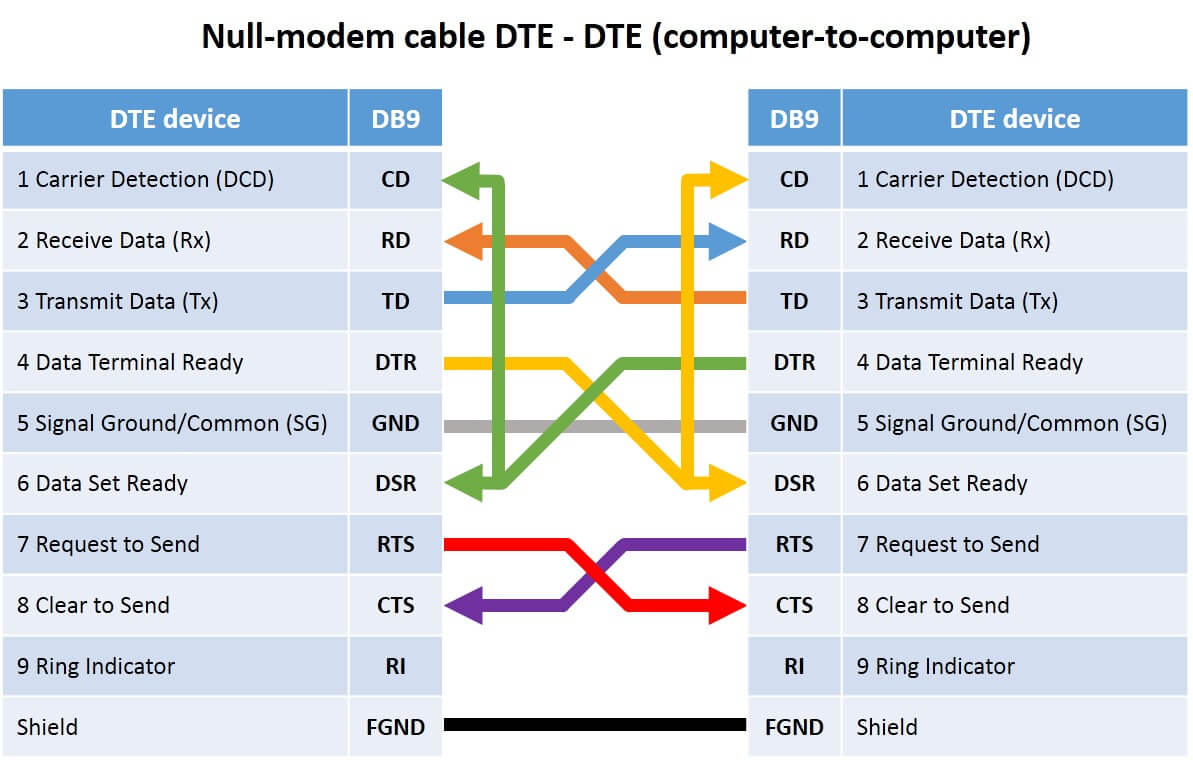
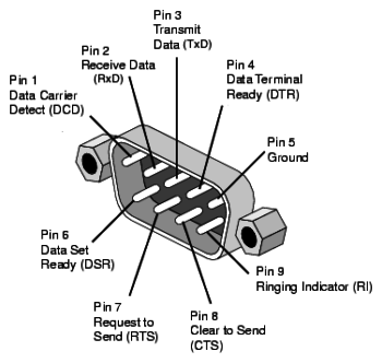
Serial interface pin assignment. 9 pin d sub female connector.

Bm 1348 Din 8 Pinout Diagram Also Rs485 Rj45 Pinout On
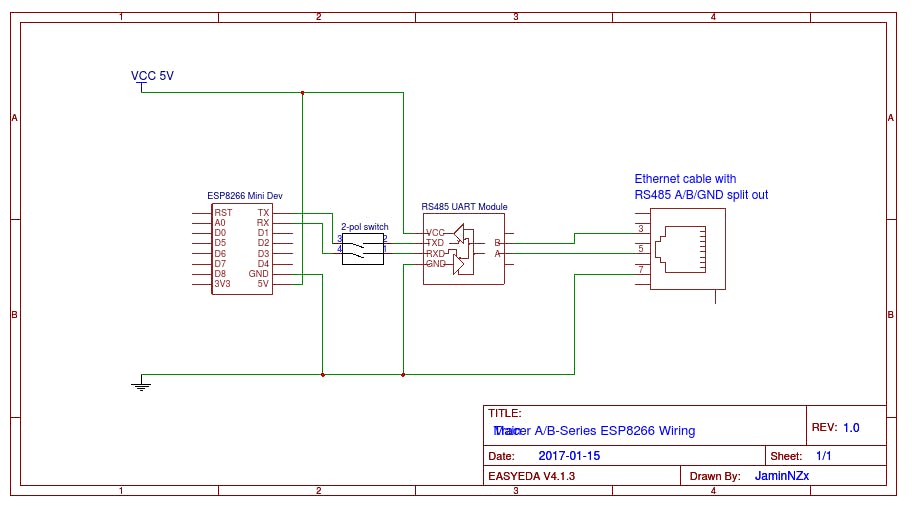
Rs485 9 pin wiring diagram. The following diagrams show the recommended schemas for 2 wire and 4 wire configurations for farsync cards such as the farsync flex and farsync t2ee. Poor shielding or earthing is a very common wiring error. Figure 3 is an rs485 wiring diagram for rs485 pinout db9 connectors. Rs485 recommended wiring. This communications mode is typically used for point to point communications over long. The txd and txd lines carry transmit data while the rxd and rxd contain the receive data.
The distances these signals are carried is greater due to differential signals. This connector is found on national instruments one and two port serial interfaces. In addition to the data wires it is worth considering whether to use a shielded cable braidfoil connected to signal earth. The following document describes the functions of the pins on the rs 485 9 pin sub d connector used in serial communications. The de 9 connector is the most common serial connector. 09013 page 3 of 3 references.
It can span relatively large distances up to 4000 feet. Because rs 485 signals are transmitted over twisted pair cabling the connections are less sensitive for noise. Pinouts devices connectors. M12 connections sub d 9 pin connector. Rs232 to rs485 cable pinout. Pinouts rs 232 and other serial ports and interfaces.
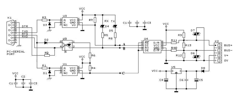
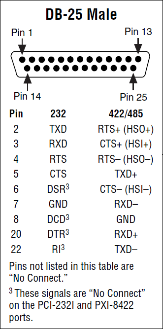
Switch settings for rs 422 4 wire full duplex switch position 1 rs 422 2 echo on 3 4 wire 4 4 wire figure 2. Pinout diagram for de 9 connector to perform a loopback test with no hardware flow control you will need to connect pins 2 and 3 for rs 232 and pins 4 to 8 and 5 to 9 for rs 422485. Pinout of rs232 to rs485 cable and layout of 9 pin d sub female connectorelectrically isolated rs485 communication interface to the pc serial port. 1 rs485 wiring diagram i the 2 cores in the twisted pair cable carry the data line plus normally red and minus normally green or b line and a line and are surrounded by the. Rs 485 4 wire full duplex diagram rs 422 4 wire full duplex. Figure 4 is a pin diagram for both 25 pin rs485 pinout half duplex and full duplex pinout connectors.
Gallery of Rs485 9 Pin Wiring Diagram


.aspx)