White the rpm input wire. 1996 evinrude 40hp parts used in this test.
Draw Your Wiring Rpm Meter Diagram
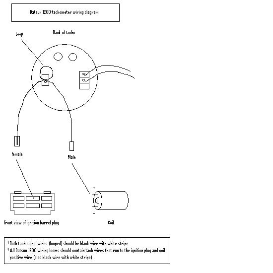
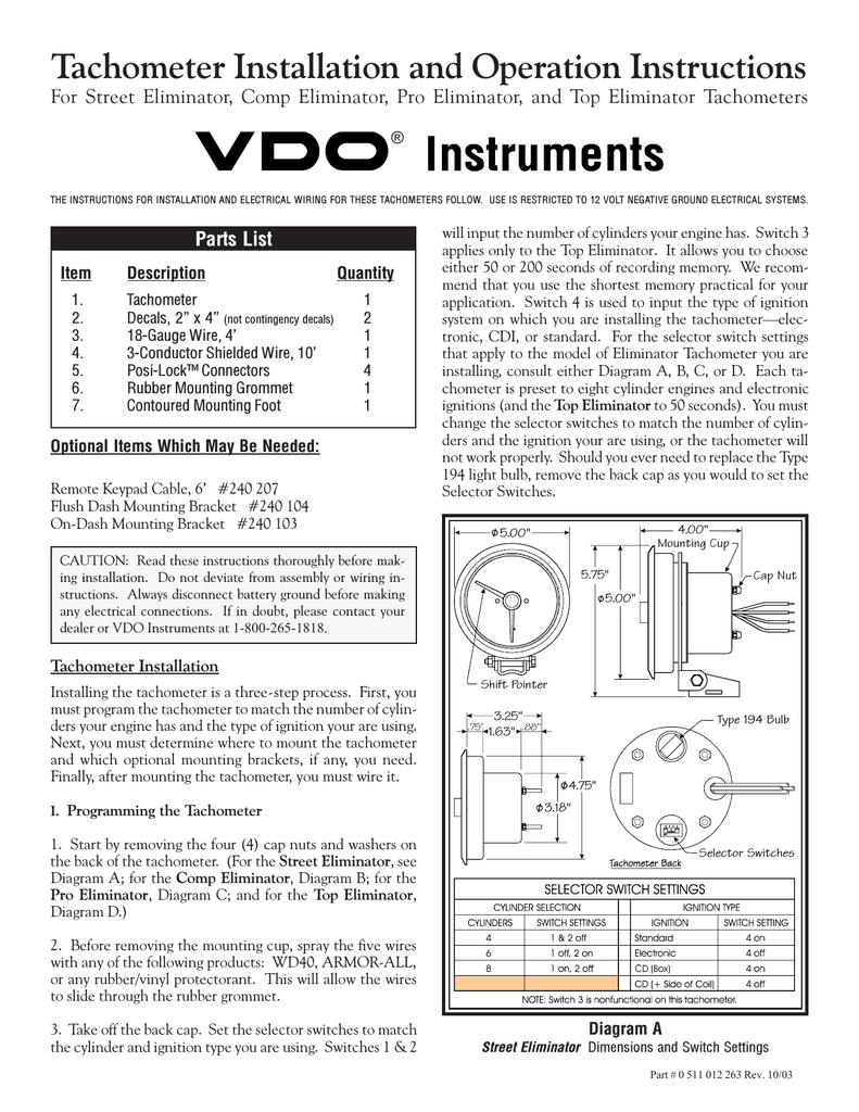
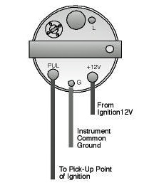
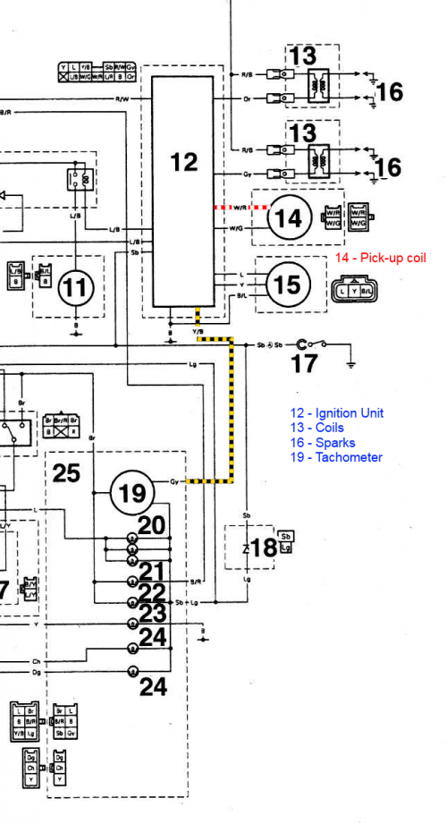
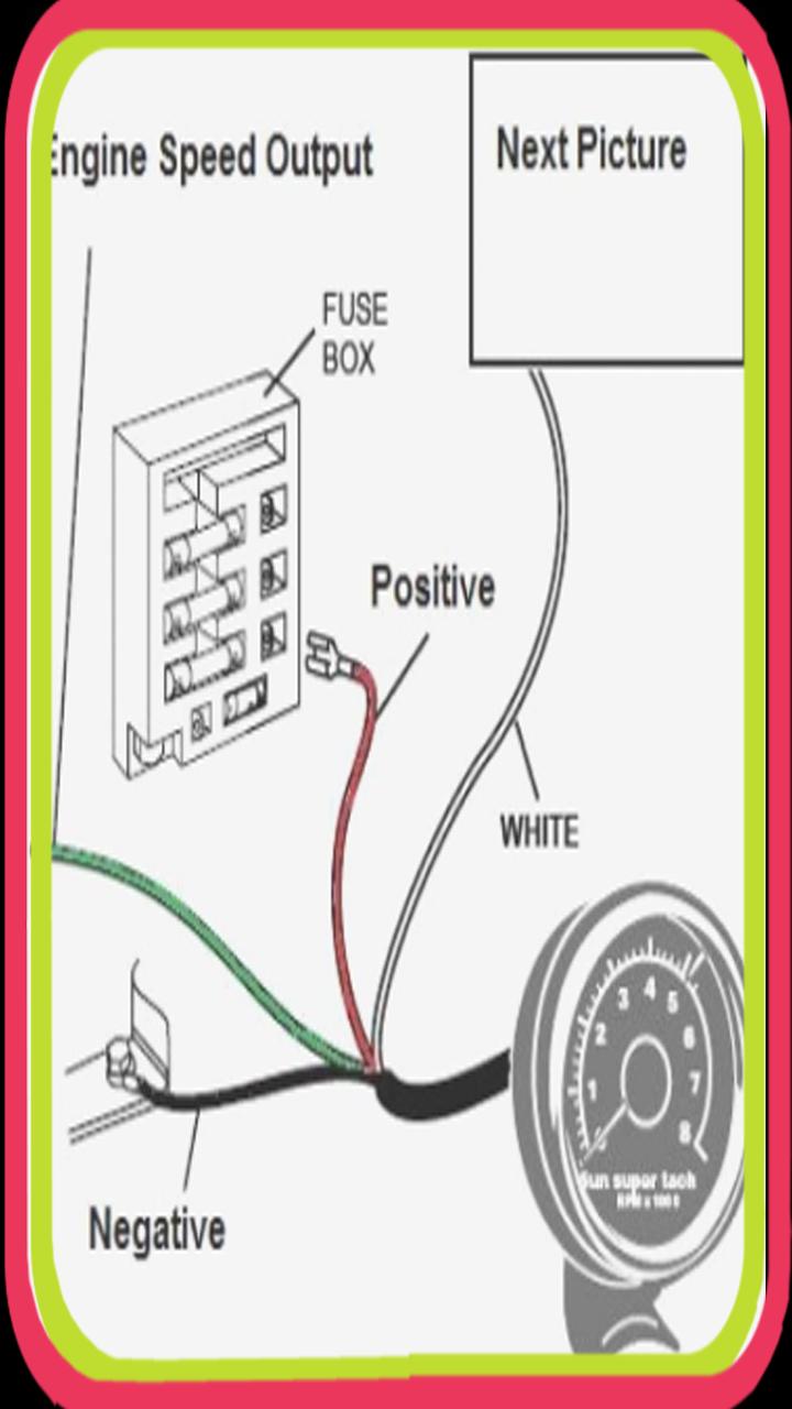
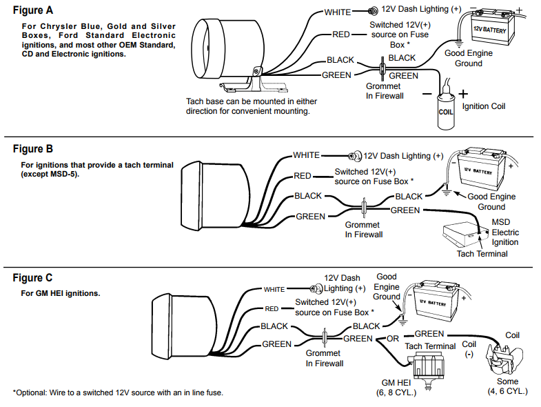
Rpm wiring diagram. Download your wiring diagrams here. More about the function of tachometer can be read in the article what is tachometer function on vehicle. On inductive ignitions it connects to the coil negative terminal. Black connects to ground. Cable dca analog cable diagram. Dual function cable srpm and digital.
Cable dcr rpm cable. Yellow this is an activation wire and is normally open and will switch to ground. The rpm device must be rotated by the display down then the correct wires according to the diagram on the back. Wiring red connects to a switched 12 volt source. Wiring diagram for aftermarket tachometer a tachometer is gauge to measure mechanical speed in units of rpm revolutions per minute or rotations per minute. The wiring basics of connecting a tachometer rpm gauge to an outboard motor.
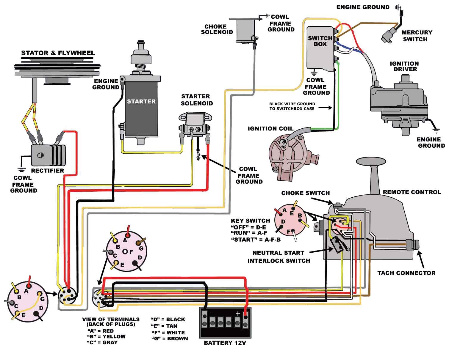
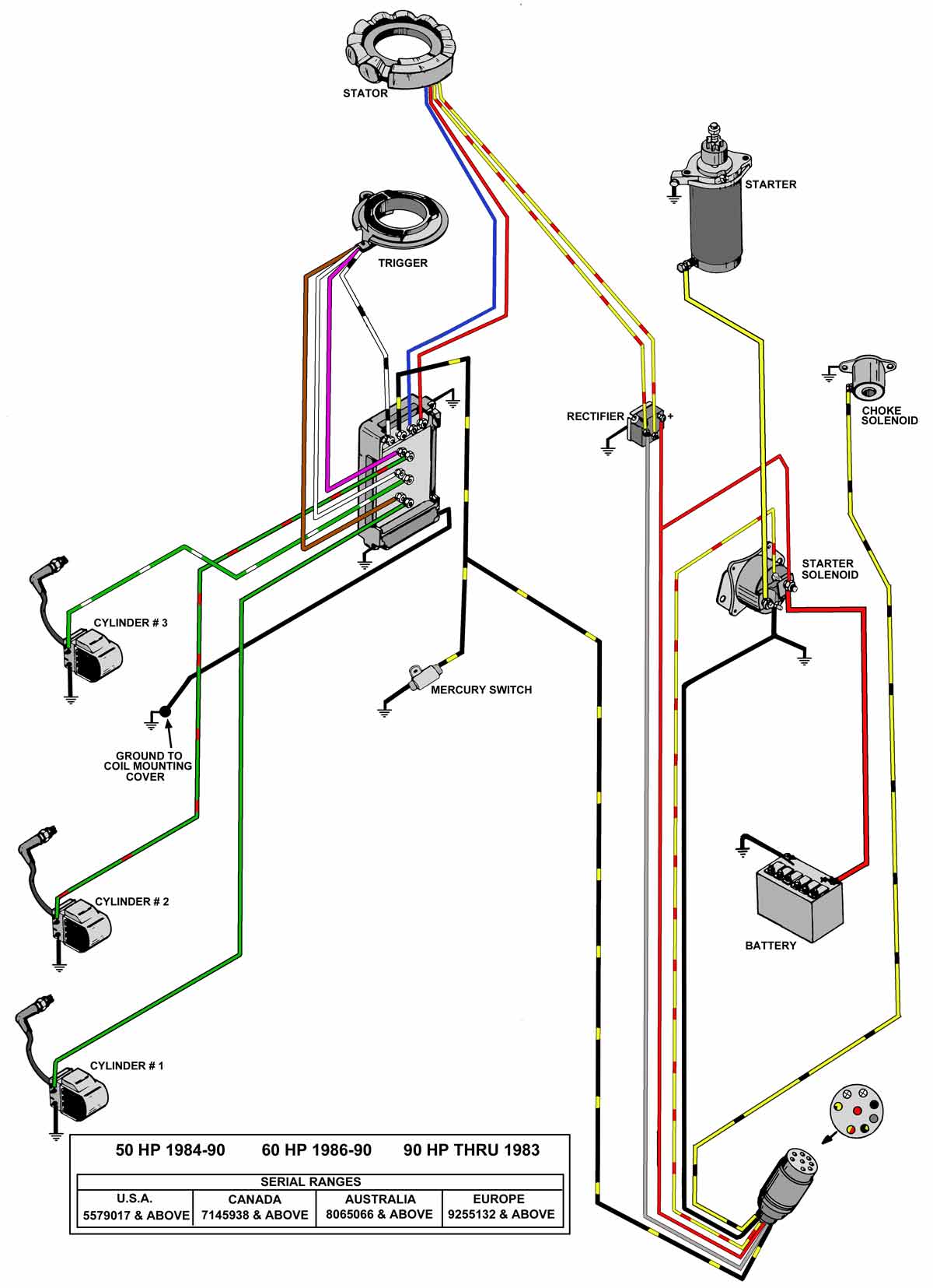
Rpm module to tach terminal white on ignition box black to ground to 12v to transbrake switch or transbrake solenoid terminal on delay box blue red yellow for factory ignitions this wire connects to coil negative. Outboard engine wiring series links. On vehicle tachometer is measuring engine speed. With an msd ignition this connects to the tach output terminal. Outboard motor control wiring part 1. Shifnoid wiring diagram shifnoid ncrpm3000 rpm switch with delay c shifnoid ltd 2011 shifnoid rpmswitch wdelay r 12v 12v 12v.
Cable dcp power and remote start cable. Cable dcrc custom rmp cable. Here is a description of electrical wires on connector. Cable dcf flowmeter cable. The positive power pole is connected to the brown wire for the magnetic sensor negative power pole speed sensor blue wire from the sensor fourth position nothing connect.
Gallery of Rpm Wiring Diagram