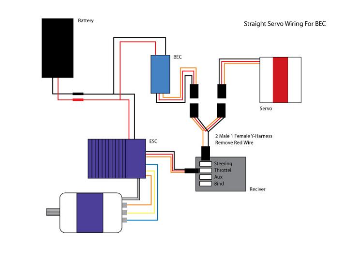
In futaba hitec and jr radio servos the servo and battery connections have the same polarity and signal wiring although the connectors are slightly different. The most common colour code is black 0 volts red 5 volts and white signal the red positive wire being the central one.

Interfacing Servo Motor With Atmega32 Atmel Avr Microcontroller
Rc servo wiring diagram. How to solder servo wire extend wire duration. I studied electrical engineering and a lot of other things. Rc simple 3 servos hexapod walker. You can mix futaba servos with an airtronics receiver mix hitec jr servos with a futaba receiver etc. Servos usually have a three wire ribbon lead. By rc lover san in circuits arduino.
Remote control quick tips considerations when buying a radiotransmitter duration. For futaba hitec and jr radio the servo and battery connections have the right polarity and signal wires although the connectors are physically different. 0 10v control for rc servos. As long as you are careful about polarity. In addition to this you need an adjustable 0 10v control voltage source. Somewhere along the line the wiring didnt become compatible.
Rc simple 3 servos hexapod walker. By rc lover san follow. You can mix futaba servos with an airtronics receiver mix hitec jr servos with a futaba receiver etc. Im always driven by my passions. This circuit takes standard 0 10v control voltage. The kit for installing a servo consists of rubber grommets brass bushes and flanged screws.
Beware of older sanwa servos which had the black negative line central. More by the author. The pinouts used on differnet servo motors vary but the wire colors are generally so that black is ground read is power and the third wire is the control input.
Gallery of Rc Servo Wiring Diagram


.jpg)