Page 12 and 13. It is important that this installation and service manual be reviewed thoroughly before operating the system.

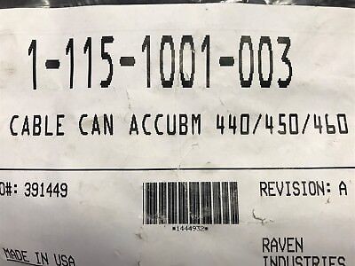
Raven 1 115 0159 858 6 3 Boom Flow Cable 3 Pin Weather Pack
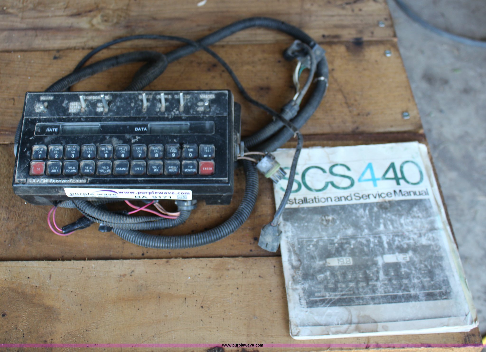
Raven scs 440 wiring diagram. Cable control console 10 115 0. Page 10 and 11. Utilizing a computer based console a speed sensor a flow meter and a control valve the scs 440 also functions as an area monitor speed monitor and volume totalizer. Our goal is to empower you our customer by providing the tools necessary to resolve issues. Raven industries is not responsible for damage to any associated equipment or products and will not be liable for loss of profit or other. Summary of contents for raven scs 440.
Page 14 and 15. Raven industries will not assume any expense or liability for repairs made outside our facilities without written consent. The raven scs sprayer control system is designed to improve the uniformity of spray appendix 3 for alternate plumbing diagram. Cable radar interface dickey john. Welcome to the raven knowledge base. The database is a searchable library containing information relating to our products and services.
Its performance relies on the installation and preventive maintenance of the complete sprayer. 22 scs 440 console 063 0159 531 scs 440 console serial interface 063 0171 183. They will continue to be available upon request. Cable flow control scs 7106 boom. The raven scs 440 sprayer control system is designed to improve the uniformity of spray applications. Cable 12 adapter rogator to raven valve control console 10 scs wiring diagram booklet rev.
The raven scs 440 sprayer control system is designed to improve the uniformity of spray applications. This manual provides a simple step. Cable flow control scs 4506 boom. Page 18 and 19. 11082018 11082018 5 comments on raven 440 wiring diagram. Cable 12 adapter rogator to raven valve control console 10 scs these instructions cover micro trak directconnect kit installation for raven sprayer control.
This manual provides a simple step. The following cable wiring diagrams were removed from a previous version of this manual. Its performance relies on the installation and preventive maintenance of the complete sprayer. 115 0159 572 cable 12 adapter rogator to raven valve 115 0159 597 cable boost valve relay 115 0159 620 cable flow adapter single channel simulator. Raven scs 440 is designed to provide uniformity of spray applications regardless of the vehicles speed. The following cable wiring diagrams.
2 connect the flow control cable connectors to boom valves flow meter and motorized leads or any other electrical wiring. Cable scs 440 extension 115 0159 4. 115 0159 910 cable 24 flow control scs 440. Page 20 and 21. Page 16 and 17. New articles are added frequently and are updated as needed.
It is important that this installation and service manual be reviewed thoroughly before operating the system. Page 49 063 0159 526 display board spacer 107 0159 478 lcd display board 064 0159 428 processor board 064 0159 559 processor board serial interface 064 0159 552 connector plate. Page 1 installation service manual scs 440.
Gallery of Raven Scs 440 Wiring Diagram