Raven 440 console raven 440 console manual. Appendix 3 for alternate plumbing diagram.

Directconnect Kits Micro Trak Systems Inc
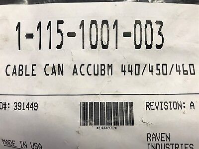
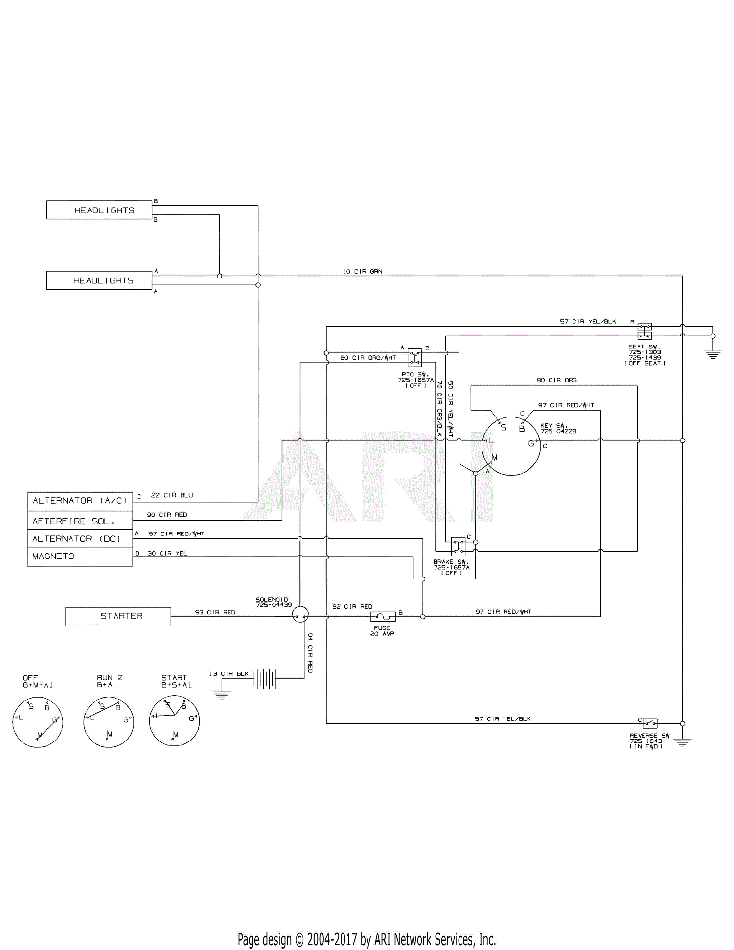
Raven 440 controller wiring diagram. New articles are added frequently and are updated as needed. Our goal is to empower you our customer by providing the tools necessary to resolve issues. 2 connect the flow control cable connectors to boom valves flow meter and motorized. The database is a searchable library containing information relating to our products and services. Raven partners with industry leading global repair facilities to help ensure a quick turn on your raven product. 4 connect the speed sensor cable to the plug in the back of the console.
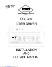
Raven 440 wiring diagram. Repair center technicians are factory trained and use raven oem replacement parts. Second where can i find a wiring diagram for the pin positions on the main raven cable looks like a rats nest with lots of extra wires spliced in. The operator sets the target volume area to be applied and the scs. Leads or any other electrical wiring. Utilizing a computer based console a speed sensor a flow meter and a control valve the scs 440 also functions as an area monitor speed monitor and volume totalizer.
Leads or any other electrical wiring. 4 connect the speed sensor cable to the plug in the back of the console. Service manual in your raven flow control product under normal use maintenance and service. The raven scs 450 is designed to provide uniformity of spray applications regardless of the vehicles speed. Please contact authorized repair centers directly before returning products to their location for repairs to ensure the repair center can repair the. Welcome to the raven knowledge base.
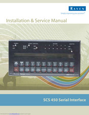
The raven scs 440 sprayer control system is designed to improve the uniformity of spray. Congratulations on your purchase of the raven scs sprayer control system 450 serial interface. Raven harness diagram welcome to our site this is images about raven harness diagram posted by ella brouillard in diagram category on nov 03 you can also find other images like wiring diagram engine diagram sensor location fuel pump location starter location control module location parts diagram replacement parts electrical diagram. Utilizing a computer based console a speed sensor a turbine type flow meter and a motorized control valve. Appendix 3 for alternate plumbing diagram. Raven scs 440 is designed to provide uniformity of spray applications regardless of the vehicles speed.
Raven 450 console raven 450 console manual. The raven scs 440 sprayer control system is designed to improve the uniformity of spray. 2 connect the flow control cable connectors to boom valves flow meter and motorized.
Gallery of Raven 440 Controller Wiring Diagram