If utility power fails the switch connects the generators power to the circuits in the generator sub panel. This simple diagram below will give you a better understanding of what this circuit is accomplishing.
Osa Compressed Sensing With Near Field Thz Radiation
Quinetic switch wiring diagram. When wiring a 2 way switch circuit all we want to do is to control the black wire hot wire to turn on and off the load. There is no longer the constraint of wiring location and. This circuit is wired the same way as the 3 way lights at this link. My trusted electrician carshalton wallington and coulsdon 35152 views 1239. The quinetic range offers an inspired solution in smart home technology. Ener j switch advantages self powered durable eco friendly and cost saving zero radiation no mainte nance no wiring saving up to 60 cost on wiring wireless switch usage fee traditional switch usage fee 6000 5000 4000 3000 2000 1000 0 material fee labor fee.
Another shed rewire quinetic wireless switching switching part 1 duration. The wiring diagram to the right will show how to wire and power this 12v 20amp on off on 3 way carling contura rocker switch. When wiring this switch you can choose if youd like to illuminate it because of the independent lamp attached to terminals 8 and 7. Or these terminals can be ignored for non backlit switch banks. This solves the issue of having to install switch wiring which has been a problem ever since the invention of the. Circuit electrical wiring enters the switch box.
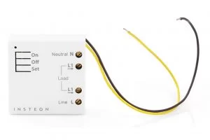
Explanation of wiring diagram 1. This transmits a signal to the receiver to turn the lamp or other load on or off. Black wire power or hot wire white wire neutral bare copper ground. With a press of the quinetic wireless switch enough kinetic energy is generated to create and transmit a radio signal to the quinetic wireless controller which in turn will switch lamps or other loads on or off. When utility power is functioning the wires from the circuit breaker in the main electrical distribution panel are connected to the generator sub panel. Three wire cable runs between the switches and the outlet.
When the switch is pressed the kinetic system transforms the movement into energy. Figure 5 wiring diagram of a manual transfer switch in the on position. Switches does not use batteries creates no wear and tear and can be used for 60 years. 3 way switched outlet wiring. Featuring wiring diagrams for single pole wall switches commonly used in the home. The kinetic wireless switch has a built in micro energy generator.
The source is at the sw1 where the hot is connected to. The worlds first wireless kinetic energy switch. How to wire a single switch. In this diagram two 3 way switches control a wall receptacle outlet that may be used to control a lamp from two entrances to a room. Switch wiring shows the power source power in starts at the switch box.
Gallery of Quinetic Switch Wiring Diagram