Refrigerator start relay wiring diagram refrigerator start relay wiring diagram every electric structure is made up of various diverse parts. Sethtuckerptc wiring diagrams represent the physical layout of an electrical circuit design.

Ptc Wiring Diagram
Ptc wiring diagram. Assortment of passtime wiring diagram. Replace all panels on unit. Attach the wiring label supplied with the kit to the unit control box cover near the unit wiring label. Views 2643 views difficulty level introductory jay aurila ptc. In the ptc relay wiring diagram. Otherwise the arrangement wont work as it ought to be.
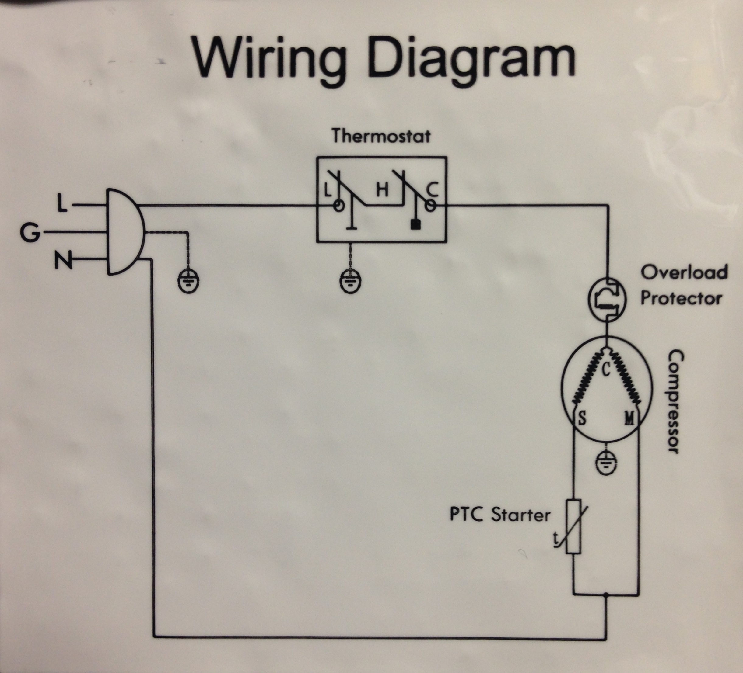
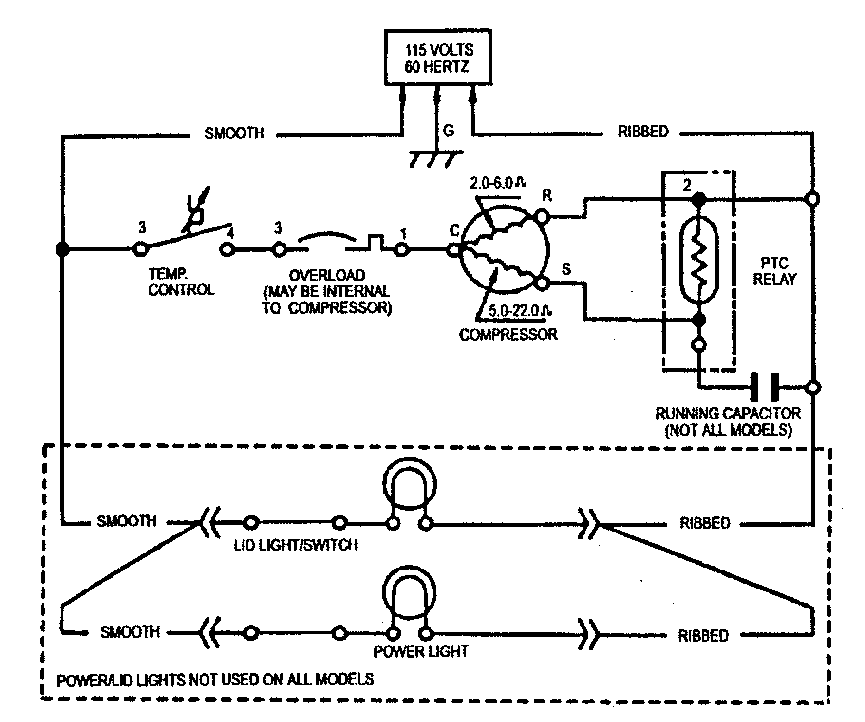
View the full course. You can create them by instancing items from a design catalog and routing wires. Each component should be set and connected with other parts in particular way. In simple words the refrigerator ptc relay gave a current to start winding and when the motor stat up the ptc compressor relay remove the start winding from the circuit. This tutorial is part of a course. It shows the components of the circuit as streamlined shapes as well as the power and also signal connections between the gadgets.
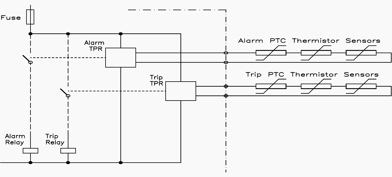
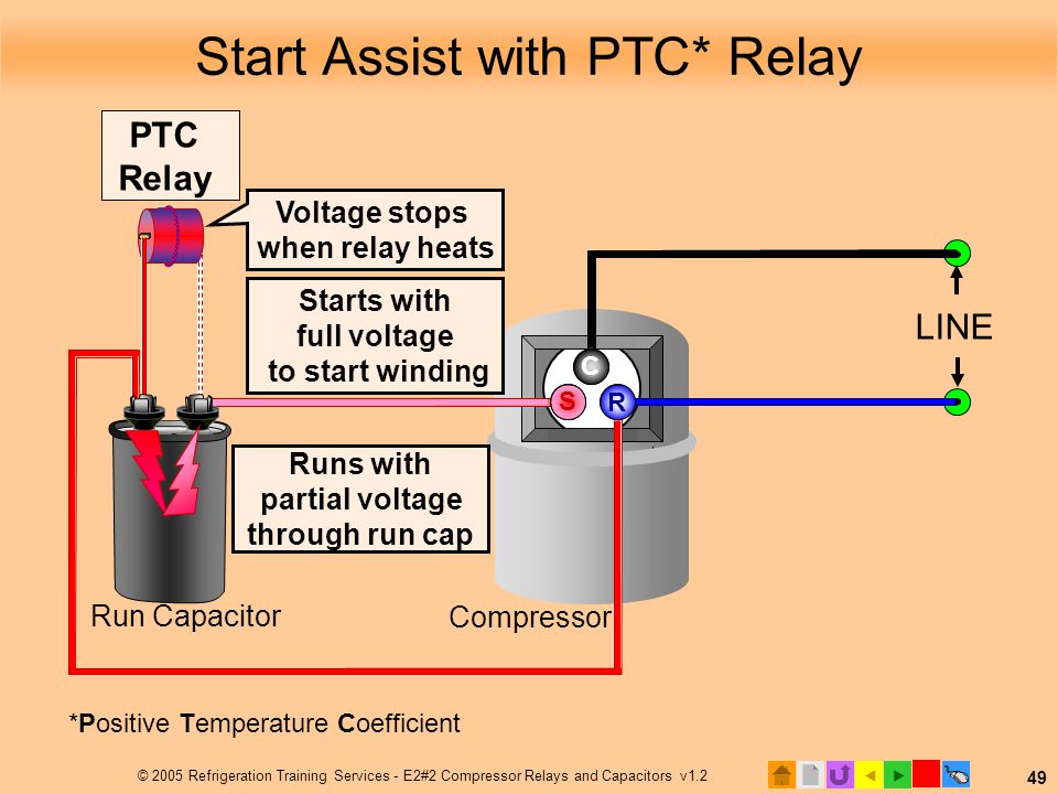
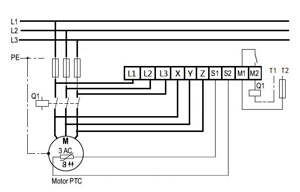
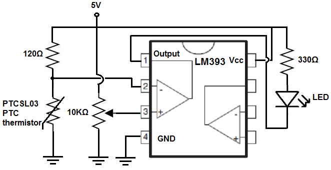
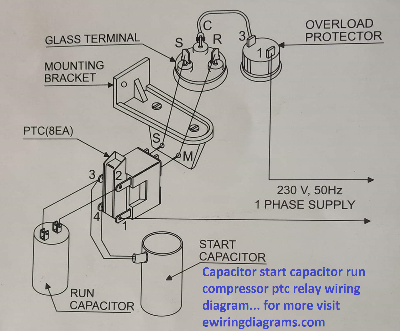
A complete connection shown that how to connect the starting and running capacitor to a compressor ptc positive temperature coefficient relay. Thermistor protection relays are required to trip reliably. The resistance is monitored by a thermistor protection relay tpr and when the sharp change in resistance is detected by the thermistor protection relay tpr it operates a contact to initiate an alarm or to trip the protected device. How to create wiring diagram in creo schematics hi jim i followed the get started tutorial in schematics but at the most interesting point routing the cables in 3d they asked to find a directory that doesnt exist on my computer see attached file. In this procedure you use wiring diagrams to represent the physical layout of an electrical circuit design. This post is about the capacitor start capacitor run compressor ptc relay wiring diagram.
Hide this message return to recommendations close close close close close creating wiring diagrams. Figure 1 ptc start. At the set point a temperature rise of a few degrees results in a large increase in resistance. Capacitor start capacitor run compressor ptc relay wiring diagram habib ullah 819 am this post is about the capacitor start capacitor run compressor ptc relay wiring diagr. Push ptc thermistor into its holding clamp. Refer to figure 1 3.
So the above is a simple and short explanation of refrigerator relay and its working so lets know the working method of a ptc. Use other 2 wires to connect center terminal and either 1 of end terminals to run capacitor. A wiring diagram is a streamlined standard pictorial depiction of an electrical circuit.
Gallery of Ptc Wiring Diagram


.png)