Rtd pt100 3 wire wiring diagram what is a wiring diagram. It is in simple terms a resistance that changes with temperature.

Pt100 Temp Sensor Wiring Diagram Wiring Library
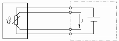
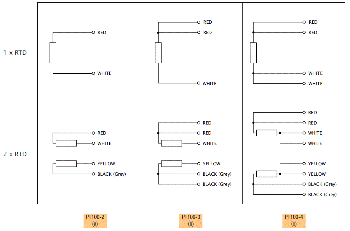
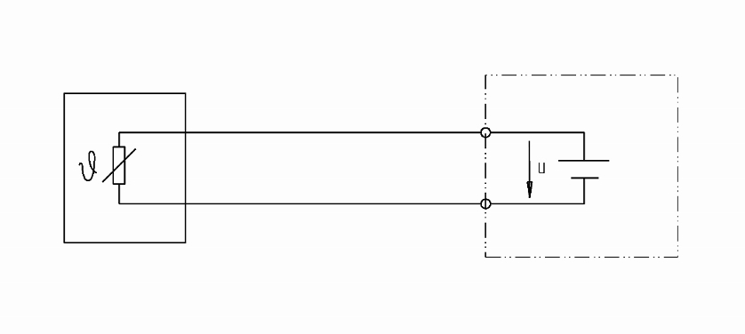
Pt100 wiring diagram. Normally if you want to measure a resistor you just connect your. Rtd wiring configurations there are three types of wire configurations 2 wire 3 wire and 4 wire that are commonly used in rtd sensing circuits. 3 wire pt100 rtd sensor wiring system. 3 wire pt100 wiring diagram wiring diagram is a simplified agreeable pictorial representation of an electrical circuit. It is very important that each of the three wires used in the measuring circuit are equal in terms of both conductor size and length. Well explain the 4 wire version since thats the most complex.
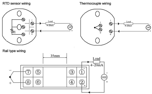
Pt100 temperature sensor wiring diagram. Resistance temperature device linear resistance change with temperature positive temperature coefficient wire wound or thick film metal resistor over limited temperature range. The addition of a third wire connected to one side of the measuring element helps to compensate for the lead resistance. Because a very small change in resistance happens with each degree in temperature the. Assortment of rtd pt100 3 wire wiring diagram. When wiring with two wires first jumper across a1 and b1and a2 and b2 respectively then connect pt100 sensors and to the rtd module according to the following diagram on the left.
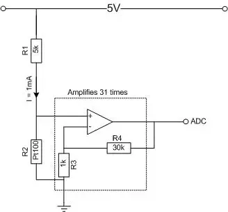
Just a small strip of platinum that measures 100 ω or 1000 ω exactly at 0 c. With a cross section of 05 mm 2 the line resistance is only 0036 ωm or 01 cm. Rtd wiring config. It shows how a electrical wires are interconnected which enable it to also show where fixtures and components may be coupled to the system. A 2 wire configuration with a compensating loop is also an option. It shows the components of the circuit as streamlined shapes and also the power and also signal links between the gadgets.
Bonded to the pt100pt1000 are 2 3 or 4 wires. A further possibility to substantially decrease the influence of the cabling is to increase the conductor cross section. It is called a pt100 because at 0 deg c it will measure 100 ohms. Both options 34 wire connection or increasing the cross section lead to a higher cost in the cabling which can be problematic especially in cost sensitive markets such as machine building. Where do those wires go pt100 1. A wiring diagram is a straightforward visual representation of the physical connections and physical layout of your electrical system or circuit.
Rtd sensors most common pt100. Rtds are really very simple devices. It shows the components of the circuit as simplified shapes and the faculty and signal friends amongst the devices. At ambient it will be around 138 ohms. 2 wire rtd connections the 2 wire rtd configuration is the simplest among rtd circuit designs. Wiring there are 2 wiring methods for the rtd module and pt100 temperature sensors two wire and three wire connections.
A1b1 a2b2 and c1c2. A wiring diagram is a streamlined standard photographic depiction of an electrical circuit. A pt100 normally has 3 wires.
Gallery of Pt100 Wiring Diagram