A wiring diagram is a simplified traditional pictorial depiction of an electric circuit. Compressor unit ground external or.

Psc Compressor Wiring Diagram Diagram Base Website Wiring
Psc compressor wiring diagram. Electrical wiring diagram psc external overload electrical wiring diagram psc internal overload electrical components use only new electrical components specific for this compressor model. Plastering a new finish coat sand finish and texture plastering tips to minimize cracking stucco duration. This video making for learning ac repairing work for new technician and for helping about this video in learn window ac psc wiring diagram capacitor selector switch blower motor 6 wire connection. Variety of air compressor pressure switch wiring diagram. Psc motor typical wiring diagram for a psc motor definition and characteristics. Psc motors are basically air conditioning compres sor motors and are very common up through 5 hp.
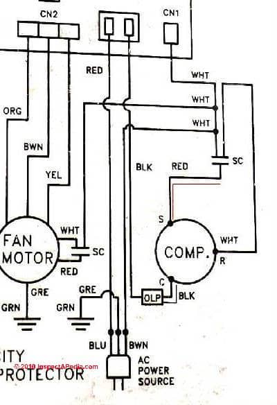
A capacitor is wired in series with the start winding. When replacing a compressor to avoid spilling any oil. It reveals the parts of the circuit as simplified forms as well as the power and also signal connections between the tools. Electrical components use only new electrical components specific for this compressor model. Psc means permanent split capacitor run capacitor permanently connected in series with the start winding run cap makes the start winding an auxiliary winding once the motor reaches running speed does not have a start capacitor. Relay potential compressor unit ground line 1 line 2 ground start winding main winding control external or internal thermal protector.
Kirk giordano plastering inc. Rotary compressor hold down nuts must be torqued to 50 inlbs to prevent loosening. The motor for the rotary compressor is a permanent split capacitor psc motor with start and run windings. Electrical wiring diagram 3 phase external rk2 rn2.
Gallery of Psc Compressor Wiring Diagram