Power packs are the heart of the low voltage sensor system. If power is disconnected to the power pack all subsequent relays will open turning off all of the loads.
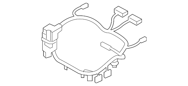
Drive Motor Battery Pack Control Module Wiring Harness
Pp 20 2p power pack wiring diagram. The pp20 transforms 120 240 or 277 volts to class ii 15 vdc to power the remote sensors. It reveals the components of the circuit as streamlined shapes and also the power and also signal links in between the devices. Dual circuit control can be handled by two pp20s one pp20 2p series 2 pole power pack or a pp20 power pack and a sp20 slave packs. For 120 vac connect the black wire to hot white wire to neutral and cap. Figure 4 7 power supply wiring diagram model m 1. Power pack pp 2par plug load control using power packs to remote sensors blk 120 v pp 2par orn 277 v pp20.
Wiring diagram for a power pack pp 20 download swtpc 69a 69k puter power supply and motherboard. Utilizing our patented relay circuit protection the pp20 also switches the lighting load on and off. Variety of wiring diagram for a power pack pp 20. Transformerless 5 volt power supply circuit diagram. The most versatile power pack is the pp20 which utilizes a patented relay contact protection and can power up to 14 sensors. 812016 20120 pm.
Wiring diagram for a power pack pp 20 wiring diagram for a power pack pp 20 download evinrude power pack wiring diagram luxury. A wiring diagram is a streamlined traditional pictorial depiction of an electric circuit. Variety of wiring diagram for a power pack pp 20. Features powers low voltage sensors pp20pp20 2p only. If wiring the local switches before the power pack and slave pack use multiple pp20s one for each circuit. Standard wiring the power pack must be connected to a single phase hot and neutral system.
Pp 20 pp 20 2p sp 20 power pack with 20 amp relay power pack with two 20 amp relays slave pack with 20 amp relay 15 to 24 vdc 15 to 24 vdc na 70 to 110 ma 35 to 70 ma 40 ma consumption model description output voltage output current add suffix lt for low temphi humidity typical applications. Variety of wiring diagram for a power pack pp 20. One sensor controlling. Power pack with 20 amp relay by sensor switch. Click on the image to enlarge and then save it to your computer by right clicking on the image. 1 5 to 37 volt 30 amp power supply.
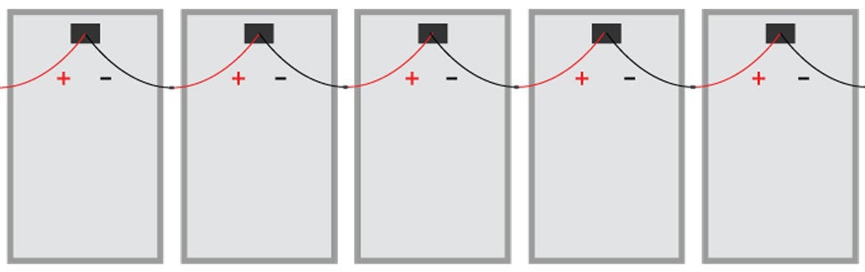
Power packs wiring diagrams blk 120 v pp20 orn 277 v blk 120 v pp20 orn 277 v. It shows the components of the circuit as streamlined forms as well as the power and signal links in between the tools. A wiring diagram is a simplified standard photographic representation of an electrical circuit. Pp 20 sp 20 pp 20 2p 120277 vac power packs slave packs n h n pp 20 load red switch blk wht wht blk orn blu blu 6. Pp20 2p is being used the switches should be downstream on the load side of the relay.
Gallery of Pp 20 2p Power Pack Wiring Diagram