Stranded ethernet cable tends to work better in patch applications for desktop use. It reveals the elements of the circuit as simplified shapes and also the power as well as signal links between the tools.

T568b Wiring Diagram Patch Panel Diagrams Within Cat 5e
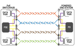
Poe ethernet wiring diagram. Otherwise the arrangement will not function as it should be. Poe integrates data and power on the same wires it keeps the structured cabling safe and does not interfere with concurrent network operation. Like you want to connect two routers or two pcs. The two standard types of poe are 8023af and 8023at. Poe is useful in situations when we want to connect network devices that are far away from a power source. Poe ip camera wiring diagram poe ip camera wiring diagram every electric structure is composed of various diverse components.
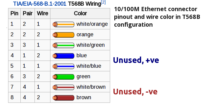
Paper focuses on the approach to optimize the ip video network with power over ethernet. Pin 7 white and brown wire. Rj45 ethernet cable pinout. Bulk ethernet cable comes in many types there are 2 basic categories solid and braided stranded cable. It is more flexible and resilient than solid ethernet cable and easier to work with but really meant for shorter lengths. Poe delivers 48v of dc power over unshielded twisted pair wiring for terminals consuming less than 13 watts of power.
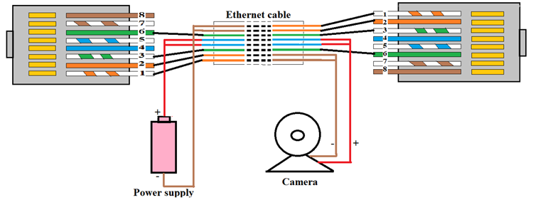
Pinout of power over ethernet poe and layout of 8 pin rj45 8p8c female connector and 8 pin rj45 8p8c male connectorpower over ethernet is a technology that allows ip telephones wireless lan access points security network cameras and other ip based terminals to receive power in parallel to data over the existing cat 5 ethernet infrastructure without the need to make any modifications. Pin 8 brown wire. A wiring diagram is a simplified conventional pictorial depiction of an electrical circuit. As others have commentedanswered the wire layout ie. Crossover ethernet cables are used to connect two devices of the same type together. Remember that pin 1 is on the left hand side of the rj45 connector with the clip at the rear.
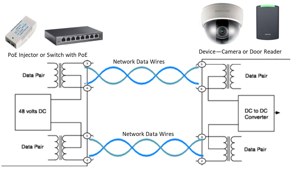
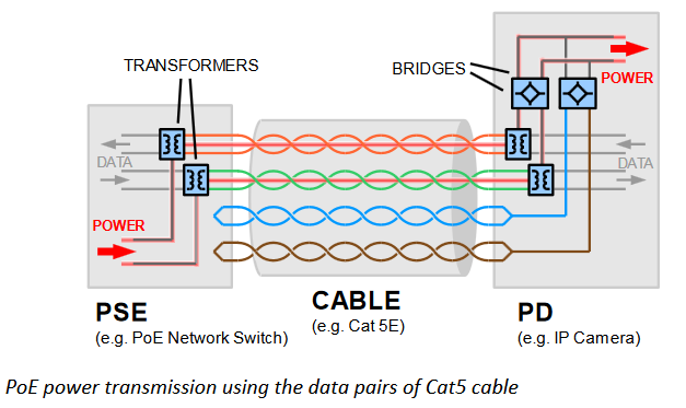
Power over ethernet ip camera wiring diagram. Power over ethernet also known as poe is a revolutionary technology that allows ip telephones wireless lan access points security network cameras and other ip based terminals to receive power in parallel to data over the existing cat 5 ethernet infrastructure without the need to make any. Collection of poe switch wiring diagram. Each component ought to be placed and connected with different parts in particular way. Ethernet infrastructure without the need to make any modifications in it. How far the signal can travel and at what speed etc so as long as the cable is poe capable any 5 cable or cat3 if less power is needed and the switchdevice is poe compliant 8023af at the color code of the wire is more for any one.
The color code doesnt matter the cable type 55e6 determines signal properties ie. Power over ethernet or poe is the technology used for power transmission in network equipment via network utp cable together with data. This allows devices like security cameras phones network switches or antennas to send and receive data and power with just one cable. In this situation we take advantage of the ethernet cable because there are 4 pairs of wires but.
Gallery of Poe Ethernet Wiring Diagram