Hydraulicpneumatic cad software motor control logic line diagram software never before has there been a cad program easier to use than ez schematics pro. In this sequence circuit pb2 is used to initiate the program.

Wiring Diagram For Bostitch Air Compressor Air Compressor
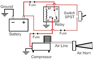
Pneumatic wiring diagram. In addition to pioneering design high impact technology and durability chicago pneumatic means customer value. Central pneumatic air compressor parts diagram. An actuator in a fluid power system is any device that converts the hydraulic or pneumatic pressure into mechanical work. Variety of husky air compressor wiring diagram. Draw the pneumatic circuit plc wiring diagram and ladder diagram to implement abb a sequence. Please call harbor freight at 1.
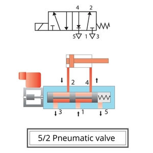
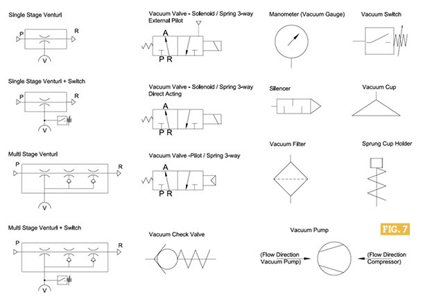
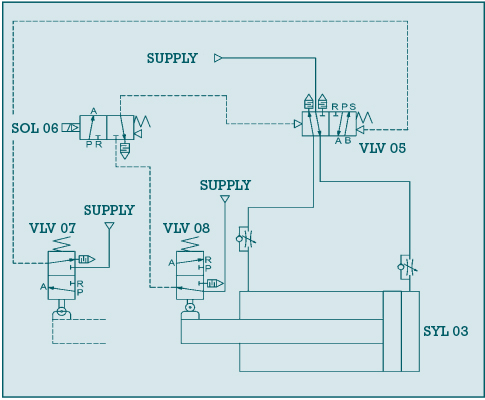
Pneumatic automatic operators are used in areas where electrically operated devices are not convenient or permitted. Consists of a modified heavy duty door. Symbols show the methods of actuation the number of positions the flow paths and the number of ports. In purely pneumatic circuits the processing of the input signals is also performed pneumatically. Check out our free libraries. Pressing pb2 causes the last memory state m4 to set and all other memory flags m1 m2 and m3 to reset.
What are pneumatic automatic operators. Initially s1 and s3 are actuated and generate outputs. Pneumatic circuit symbols explained. Air compressor central pneumatic centralpneumatic 69269 owners manual safety instructions. Moreover the heat source for a basic ac system can include heat strips for electric heat or even a hot water coil inside the. Directional air control valves are the building blocks of pneumatic control.
How to wire an air conditioner for control 5 wires the diagram below includes the typical control wiring for a conventional central air conditioning systemfurthermore it includes a thermostat a condenser and an air handler with a heat source. It reveals the components of the circuit as streamlined shapes and the power and also signal connections between the gadgets. Pneumatic circuit symbols representing these valves provide detailed information about the valve they represent. The structure of pneumatic schematics. Central pneumatic air compressor ebay 25 ft pvc air hose with fittings 595. Actuators are classified as linear actuators and rotary actuators.
Parts list and diagram if product has no serial number record month and year of purchase instead. A wiring diagram is a simplified traditional pictorial depiction of an electric circuit. Since decades chicago pneumatic has a heart for the general industry and matches your highest demands with the right solutions. The wiring diagrams are shown on page 14 of the installation instructions attached. Linear actuators have some form of piston device. If you need to draw electrical schematics or a hydraulic diagram quickly and easily this is the program you can count on.
Figure 20 fluid power reservoir symbols. Pneumatic wiring diagram. First of all you will be introduced to the chicago pneumatic way of working. In pneumatic circuit diagrams the components are arranged the way that the flow of energy always flows from the bottom up as opposed to electrical schematicsthus the pressure source represents the first element the actuator the last element.
Gallery of Pneumatic Wiring Diagram