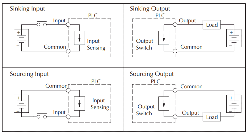
In this article we are sharing the basic concepts of plc and dcs control systems wiring diagrams for digital input di digital output do analog input ai and analog output ao signals. You will notice that the load appears between the v brown and switching wire black.
Plc
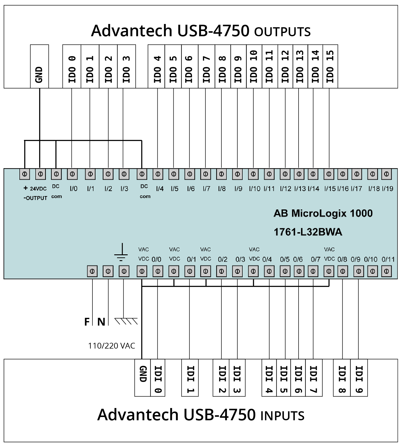
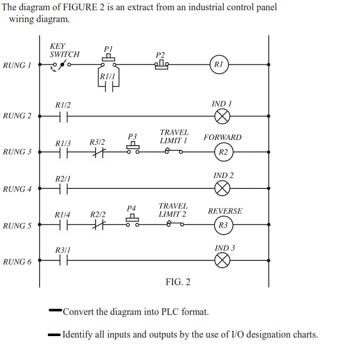
Plc input wiring diagram. The v brown will be attached to the common input and the switching wire black will be attached to the input number. Each rung must start with an input or inputs and must end with at least one output. Plc wiring 34 5 vdc ttl 200 240 vac 48 vdc 24 vac plc input cards rarely supply power this means that an external power supply is needed to supply power for the inputs and sensors. Example of wiring diagram for part of input plc input plc applied is limit switch and proximity swtich while plc applied by plc keyence. Example of wiring diagram plc following way tacking on the cable. Source of voltage for input to plc applies source of voltage dc 24 volt.
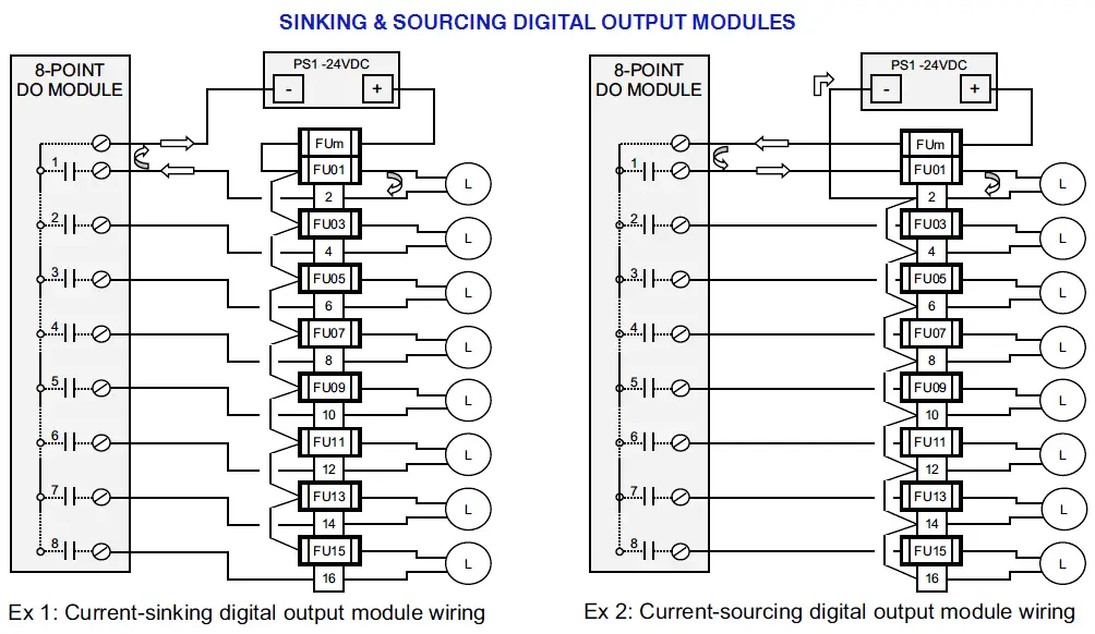
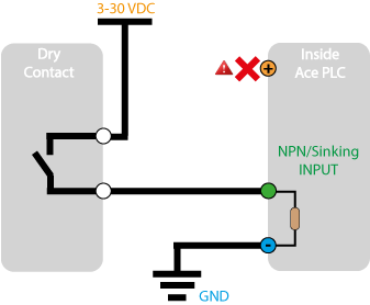
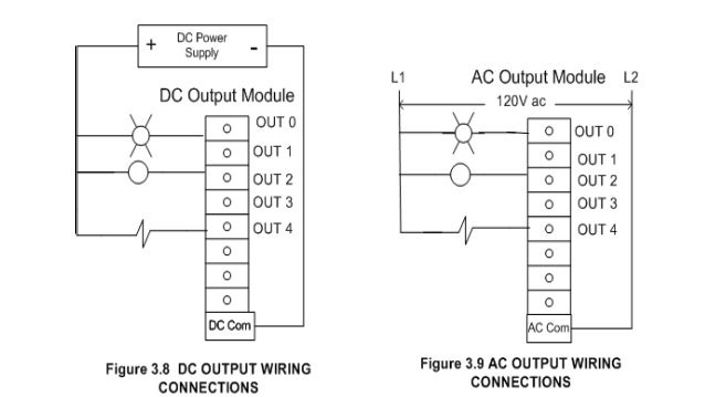
When connecting to the plc the plc input acts as the load. The term input is used for a control action such as closing the contacts of a switch used as an input to the plc. The following is a wiring diagram of an open collector npn sensor. Plc wiring diagrams guide include the discrete signals wiring plc digital input modules wiring plc output modules wiring and basics of plc terminations. Note that these diagrams are without a barrier or isolator fuses and surge protector for keeping it very simple and understandable. The term output is used for a device connected to the output of a plc eg a motor.
Gallery of Plc Input Wiring Diagram