Flashing diagram using an ftdi usbuart adapter. Altium design files the following pdf files are provided for convenience only.
Integration Of Pixracer With Optical Flow Pmw 3901 Copter
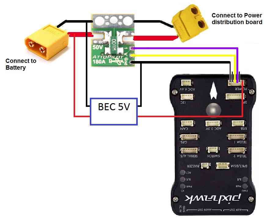
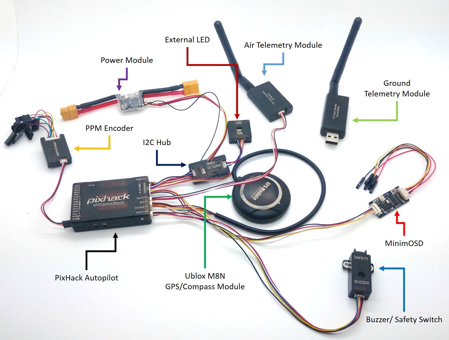
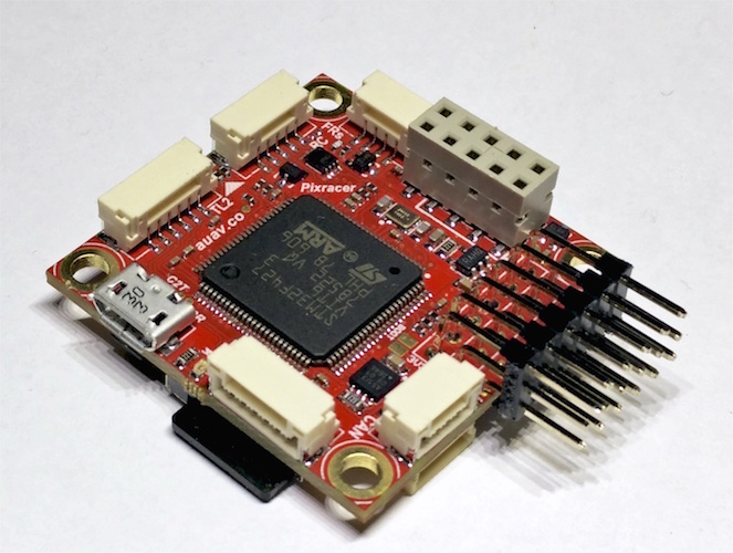
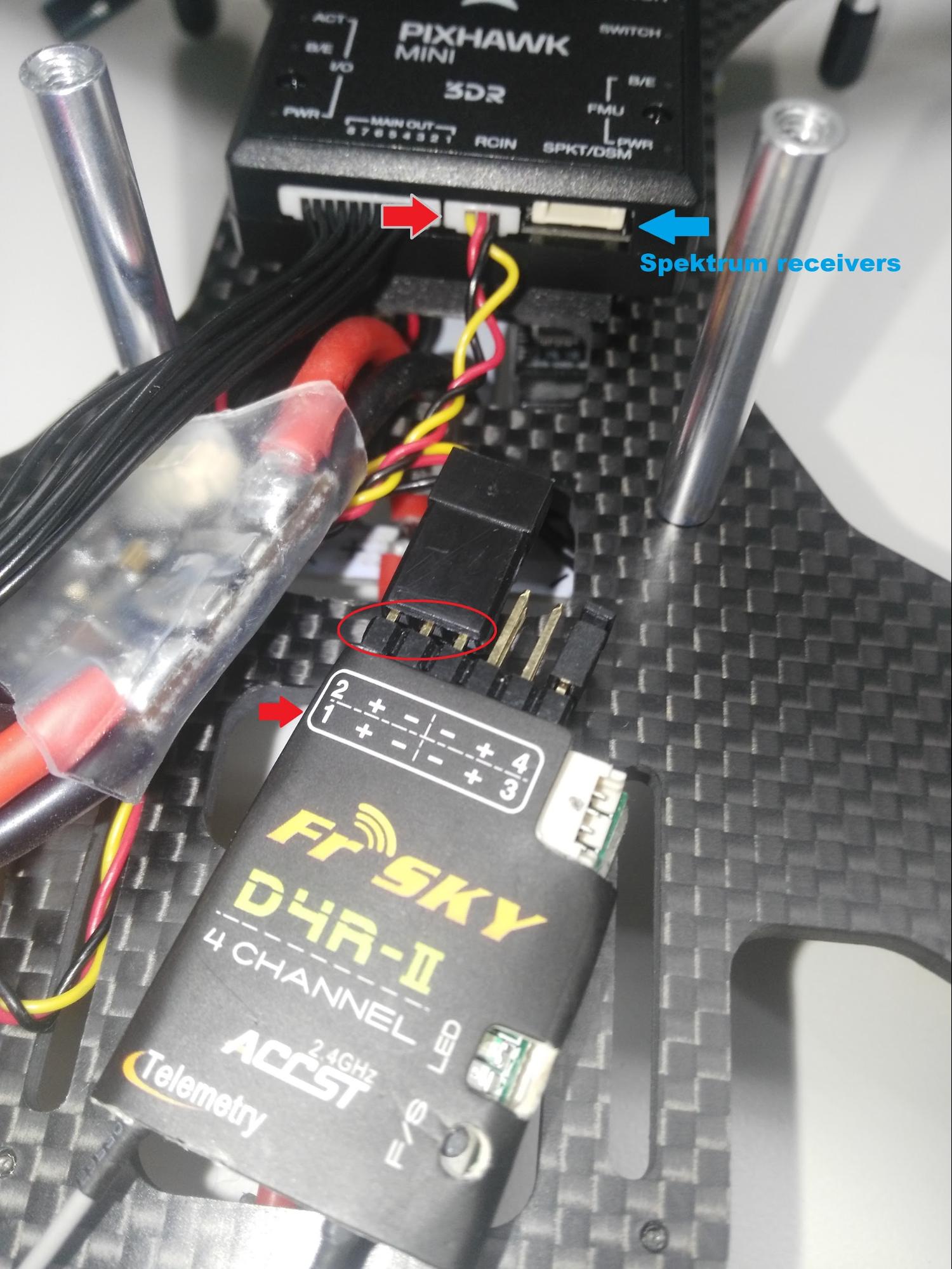
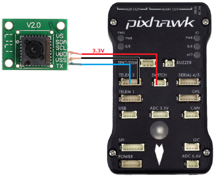
Pixracer wiring diagram. Even on the official board youll have 6 wires but 5 of them will be black and one of them is red. This is necessary to avoid current surges from motors or escs to flow back to the flight controller and disturb its delicate sensors. The reference is provided as. Power module with voltage and current sensing. Pixhawkpx4 setup configuration. Pixracer r14pdf r14 or rc14 is printed next to the sdcard socket.
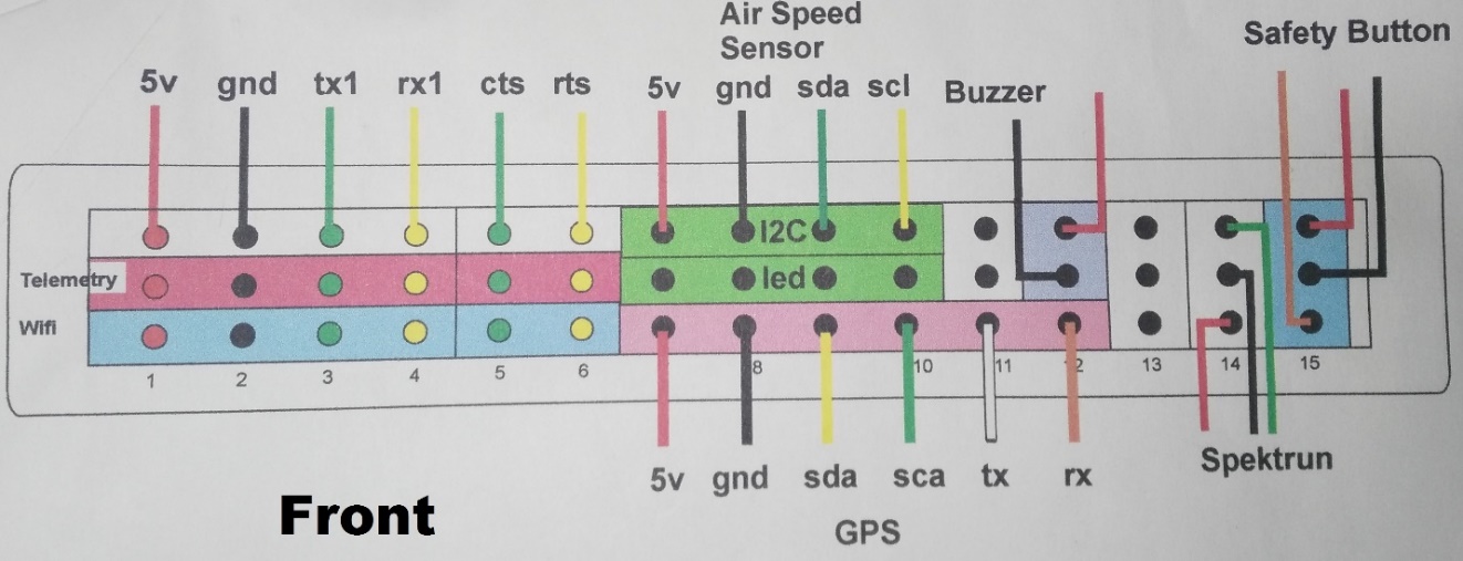
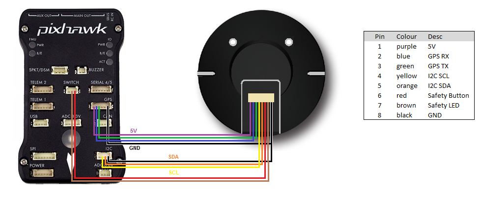
Pixhawk wiring quick start plane documentation pixhawk wiring quick start this article provides high level information about how to power pixhawk and connect its most important peripherals pixhawk wiring quickstart px4 user guide pixhawk wiring quick start the pixhawk should be mounted on the frame using vibration damping foam pads the diagram shows a bined gps. The pixracer is designed to use a separate avionics power supply. This quick start guide shows how to power the pixracer flight controller and connect its most important peripherals. Simple at 0101 in this video i show the wiring diagram for the pixracer gps port. Esp8266 must be powered with 33 volts only. If using px4 182 and earlier.
Pixracer wiring quickstart. Pixracer wiring quick start. Wiring for flashing the firmware. A remote control rc radio system is required if you want to manually control your vehicle px4 does not require a radio system for autonomous flight modes.
Gallery of Pixracer Wiring Diagram