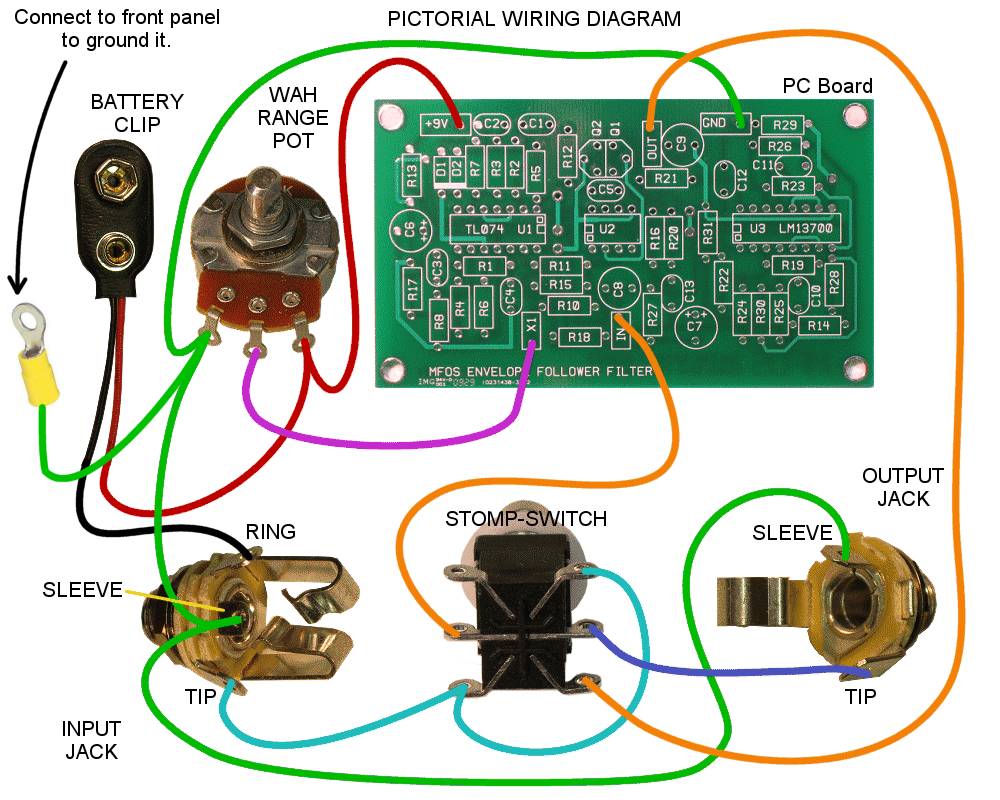
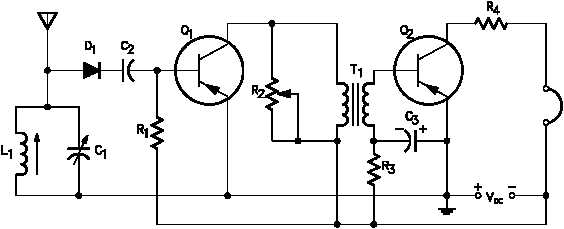
Pictorial diagram the simplest of all diagrams is the pictorial diagram. Wiring diagram or pictorial.
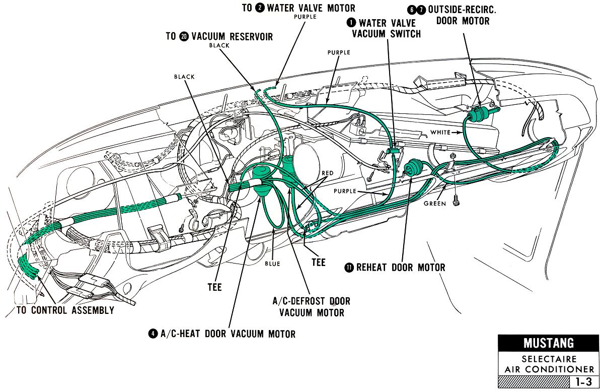
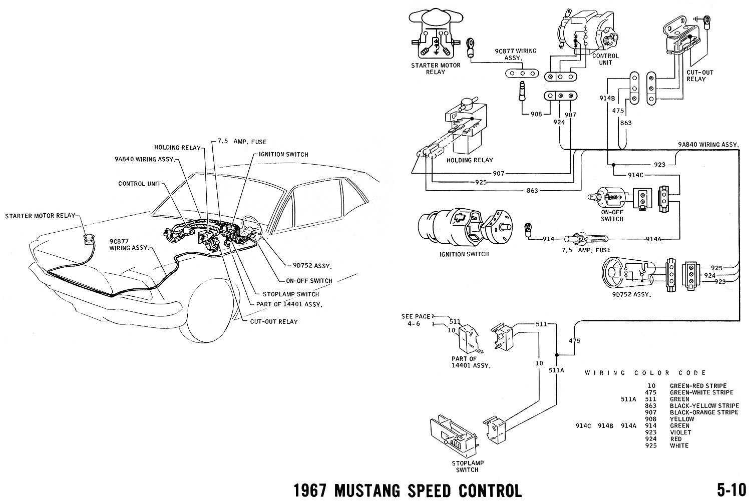
Ba313 1967 Mustang Under Hood Wiring Diagram Schematic
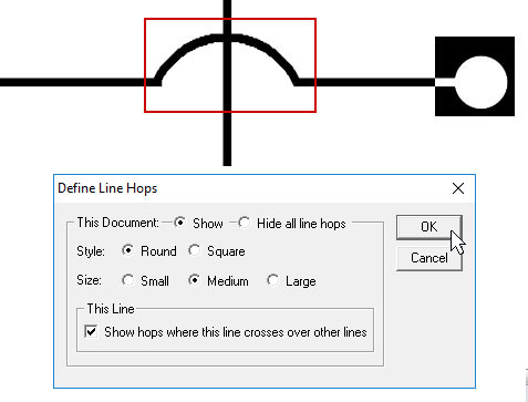
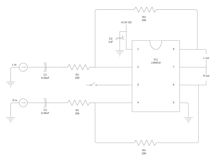
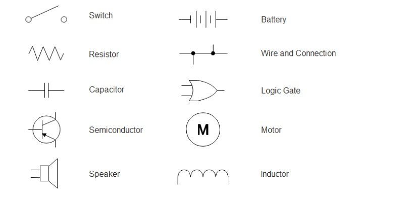
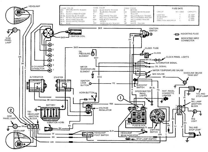
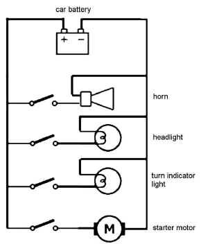
Pictorial wiring diagram. The factual diagram is obtained by the combination of pictorial wiring. Symbols that represent the components in the circuit and lines that represent the connections between them. Wiring diagrams are made up of two things. Standard wiring diagram symbols if a line touching another line has a black dot it means the lines are connected. It shows the components of the circuit as simplified shapes and the power and signal connections between the devices. Unlike a pictorial diagram a wiring diagram uses abstract or simplified shapes and lines to show components.
A simplified conventional pictorial representation of an electrical circuit. It shows the components of the circuit as simplified shapes and how to make the connections between the devices. This simplified diagram provides the means to readily identify the components of a system even if you are not familiar with their physical appearance. Diagrams will show receptacles lighting interconnecting wire routes and electrical services within a home. It reveals the parts of the circuit as simplified shapes and also the power as well as signal links between the tools. A wiring diagram is a simplified conventional pictorial representation of an electrical circuit.
Whats wiring diagram a wiring diagram is a type of schematic that uses abstract pictorial symbols to show all the interconnections of components in a system. The pictorial diagram is a picture or sketch of the components of a specific system and the wiring between these components. This includes circuit breaker boxes and any alarms that are wired into the system. A wiring diagram is a simplified standard pictorial representation of an electrical circuit. A diagram which is used by the technician to locate the components present in the control panel is called factual diagram. Pictorial diagrams are often photos with labels or highly detailed drawings of the physical components.
By using this diagram a technician can easily locate the different types of components of a control panel. Two conductors a positive from the battery switch with a fuse and a negative from the ganged together battery negatives should be ran to where the central switch panel is. This type of diagram does not show physical locations of components or the manner in which the wiring is marked or routed. The next step is to get the power from the house battery up to the switch panel where we can use it to do some good. This simplified diagram identifies components even if you are not familiar with their appearance. An electrical wiring diagram will use different symbols depending on the type but the components remain the same.
It shows a picture or sketch of the various components of a specific system and the wiring between these components.
Gallery of Pictorial Wiring Diagram