Relay contacts are isolated 8 pin. Wiring diagram book a1 15 b1 b2 16 18 b3 a2 b1 b3 15 supply voltage 16 18 l m h 2 levels b2 l1 f u 1 460 v f u 2.
Phase Failure Relay Connection Installation In Hindi Amp Urdu
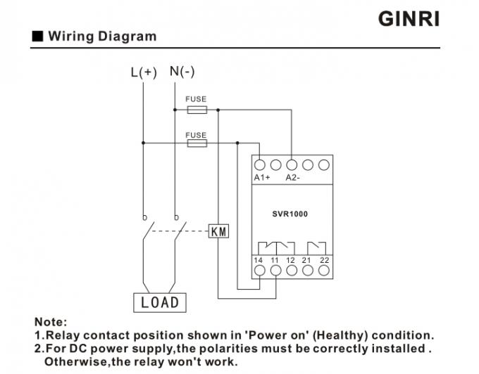
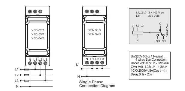
Phase protection relay wiring diagram. Works with 3 phase systems from 208v to 480v. It fit all the wires guaranteed protection against moisture. Phase to phase faults the relays in only the affected phases operate. Check the housing quality wiring diagrams photocell. 26 series screw terminal panel mount relay double phase switch 2 no dpst no 10 a contacts coil rated 12 v ac. In the presence of additional terminals designed for mounting wires installation of the part will be simple.
K ordering information example. 3 phase faults the overcurrent relays in all the 3 phases act. 0 1 2. A multi color led indicates normal. 10a spdt output contacts 8 pin octal base. Phase 1 l2 l4.
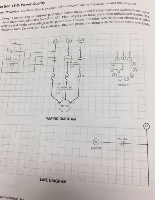
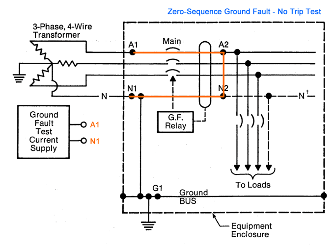
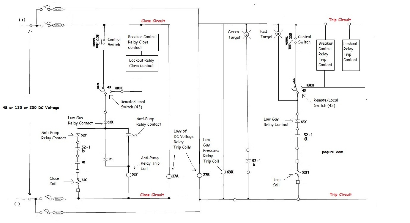
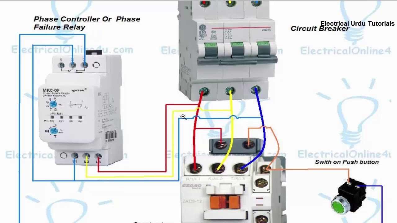
Note due to wrong connection done the above diagram is update in the above diagram i shown the complete method of wiring or connection of phase failure relay diagram with circuit breaker cont actor overload relay push button switches and electric motor however lets talk about this step by step. Voltage protection wiring diagram f fuses øa phase a l1 øb phase b l2 øc phase c l3 no normally open nc normally closed 2a fast acting fuses recommended for safety not required. If a phase failure occurs on l2 or l3 the shunt trip coil will draw power from l1 through the control relay cr contacts and phase failure relay contacts which will c hange state upon detecting a phase failure. Wiring diagram on page 5. Protection category ip 20 ip 20 ip 20 approvals according to type 3 26 seies 26 series step relays 10 a. Single line to ground faults only the relay in the faulty phase gets the fault current and operates.
1 phase 2 phase 4 wire 3 phase line markings l1 l2 l1 l3. Knowing the sequence of operation for this type of starting relay can help you diagnose confirm or rule out certain service problems. Phase monitor relay provides protection against phase reversal phase loss phase unbalance undervoltage and overvoltage. Phase 2 l1 l2 l3. Overcurrent protection for 3 wire control circuits 11 ac manual starters and manual motor. If a phase failure occurs on l1 the control relay cr c ontacts change state.
Single phase motors controls 12 1 hp crc qd relay 282 40 5015 sixth digit depends on hp control box wiring diagrams gnd green cap capacitor b l1 b main y r start l2 l1 motor leads line leads orange qd relay black yellow red blue gnd green gnd green gnd green start capacitor run capacitor cap b l1 qd relay. Know your potential starting relays this website requires certain cookies to work and uses other cookies to help you have the best experience. When installing the light barrier in the diagram is not intended terminals will be required to purchase junction box. Wiring diagrams n l accessories for 12 and 24 v dc control. 3 nos oc relay for overcurrent and earth fault protection. Can be accomplished by using the diagram below.
Gallery of Phase Protection Relay Wiring Diagram