This is the same wattage as the previous sixteen panel system and thus has a great amount of. Solar panel wiring diagram 7usage and limitations.
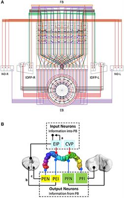
Frontiers The Topographical Mapping In Drosophila Central
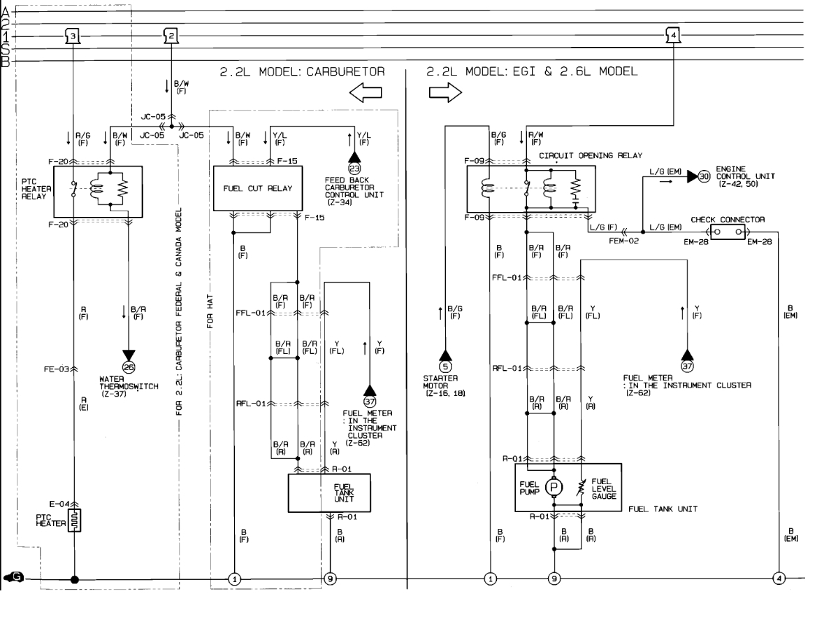
Pfi panel wiring diagram. Dashed lines indicate a single purchased component. Basics 10 480 v pump schematic. There are a few different ways to arrange panels batteries and connectors. A diagram that represents the elements of a system using abstract graphic drawings or realistic pictures. Basics 8 aov elementary block diagram. Aug 8 2016 200 amp main panel wiring diagram electrical panel box diagram.
Circuit breaker panel box wiring diagram. Basics 13 valve limit switch legend. An example of a wiring diagram for a motor controller is shown in figure 1. Note that symbols are discussed in detail later. Basics 9 416 kv pump schematic. Crane or elevator motors or any motor where the load may drive the motor or multispeed motors or motors involving open transition reduced voltage starting.
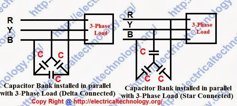
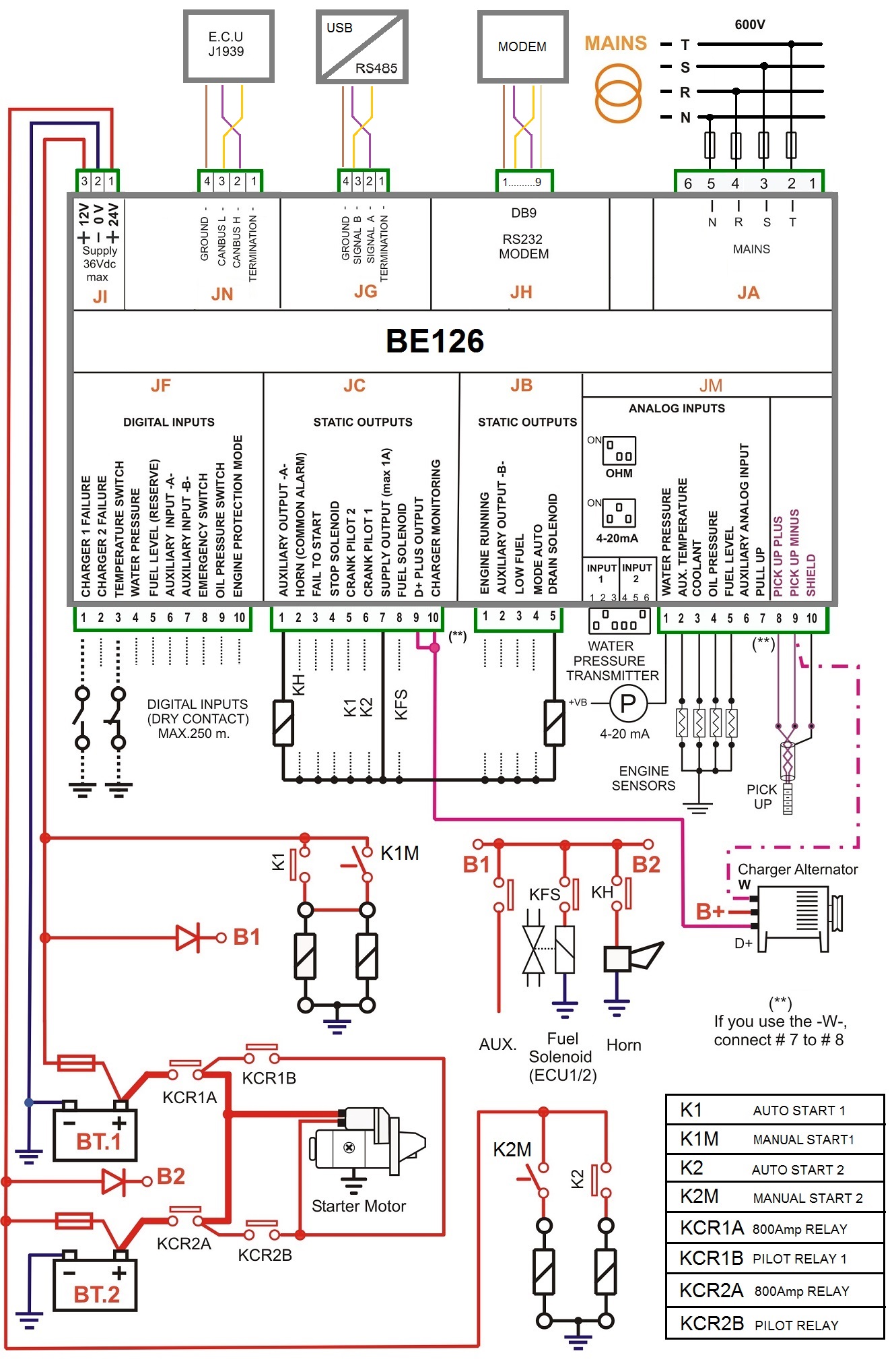
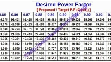
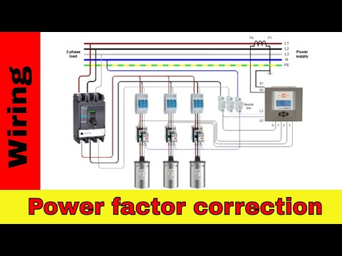
Pfi panel pfi is power factor capacitor bank power factor pfi panel how to create power factor key pfi key knowledge about pfi board connection power fa. Basics 14 aov schematic with block included basics 15 wiring or connection. Do not oversize power factor correction capacitorsdo not connect kvar units to the load side of a starter or contactor for motors subject to reversing plugging or frequent starts. This system uses 3 phase ac power l1 l2 and l3. Solar panel wiring diagrams. Use the wiring diagrams below as a guide to putting together your diy solar panel system.
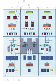
The hot wire for a branch circuit is connected to the. The breakers are installed in a panel so that contact is made with one of two hot bus bars running down the middle of the box. May 20 2017 3 phase pfi power factor improvement panel. Basics 7 416 kv 3 line diagram. Electrician circuit drawings and wiring diagrams youth explore trades skills 3 pictorial diagram. Basics 11 mov schematic with block included basics 12 12 208 vac panel diagram.
This diagram illustrates some of the most common circuits found in a typical 200 amp circuit breaker service panel box. Electrical wiring diagrams of a plc panel. Watts since we connected 16 panels together in series this solar system will output 1008w of power per hour maximum under optimal sunlight conditions. A diagram that uses lines to represent the wires and symbols to represent components. These diagrams are designed to be understood by a beginner for a safe and effective install with readily accessible components. Series wiring sixteen panel solar system.
Gallery of Pfi Panel Wiring Diagram