Numatics Valve Wiring Diagram

M23 12 19 pin and m27 26 pin pin outcolor code chart revised pin out color code chart for all i version m23 and m27 cable assemblies. Double solenoid valves always consume two solenoid outputs while single solenoid valves consume either one or two solenoid outputs depending on the internal circuit board single or double z board.

G3 Series Profibus Dp Technical Manual Asco Numatics

G3 Series Profibus Dp Technical Manual Asco Numatics

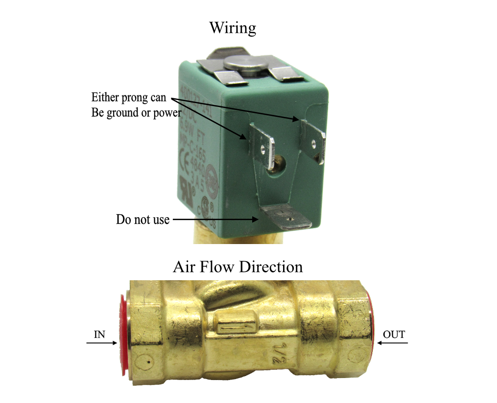
Numatics valve wiring diagram. Page 1 td500xxwd1 1en 0716 subject to change without notice. 2 z boards configured with all doubles wire to common. Electrical interface wiring data sheet. Disconnecting piping or wiring. Numatics wiring documentation diagrams and manuals. Z boards configured identical to valve type wire to common example no.

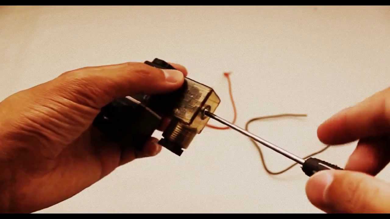
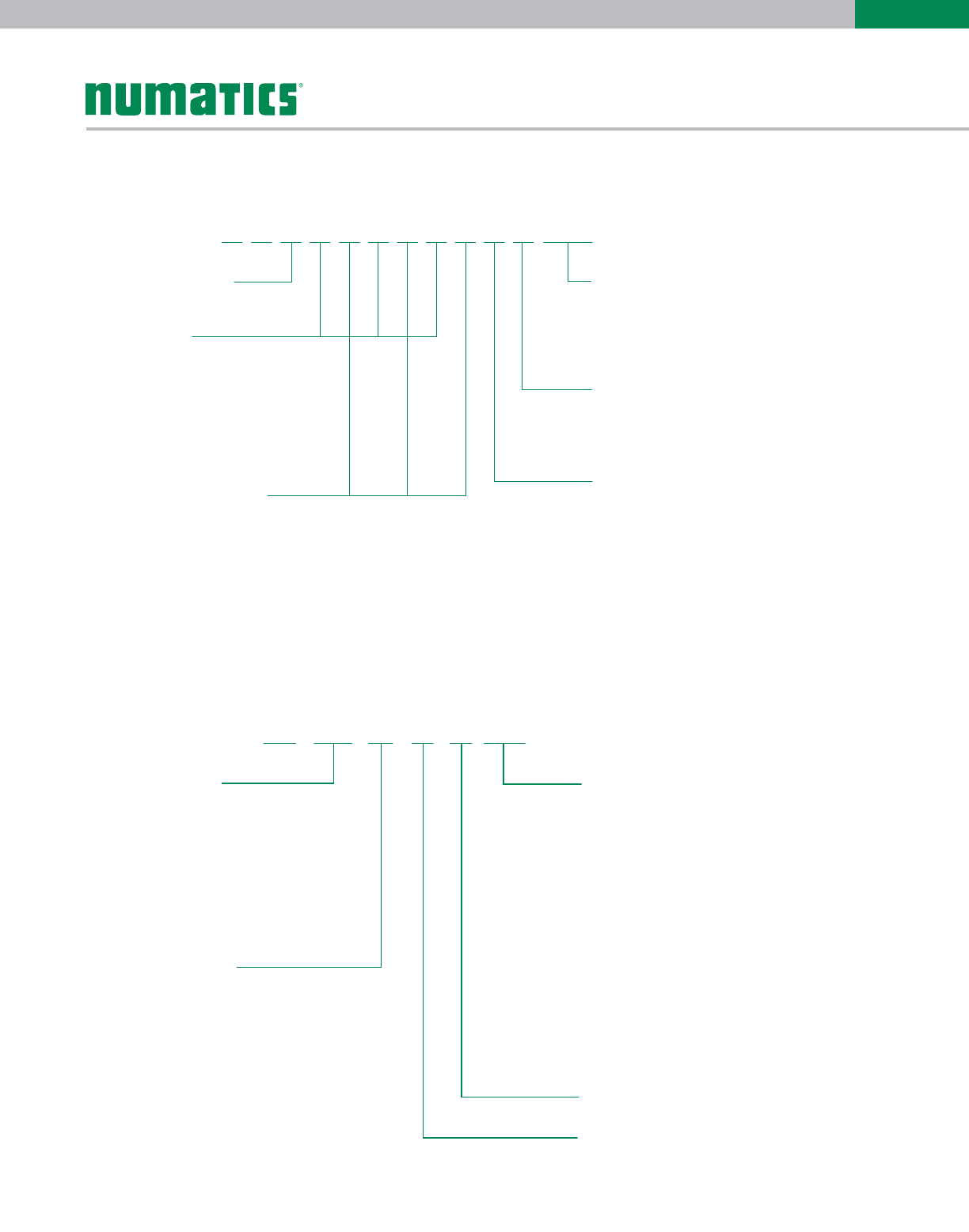
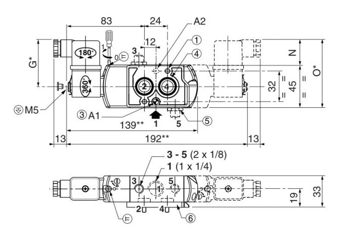
Numatics a leader the industry in valve technology with innovations that reduce installation wiring diagram of the numatics generation series air valves. M23 12 19 pin and m27 26 pin pin outcolor code chart. Wiring document for all sub d m23 and m27 connector manifolds for the generation 500 series valves. Table of contents l01 series technical and operating data 3 how to order 4 valve dimensions 5 manifold assembly 6 speed control kit 7. Override type valve function wiring option 1214 end voltage ac 2450 60 dc 100 11550 110 12060 200 23050 220 24060 12 vdc 24 vdc flush non locking override. 500 series electrical interface wiring data sheet wiring document for all sub d m23 and m27 connector manifolds for the generation 500 series valves.

M o d e l s e l e c t i o n t a b l e standard valvemounting combinations. M23 and m27 connector manifolds for the generation 2000 series valves.

Gallery of Numatics Valve Wiring Diagram

90707ed Asco Din Connector Wiring Diagram Wiring Resources
Download Now
90707ed Asco Din Connector Wiring Diagram Wiring Resources
Asco Series 502 Emerson Us
Download Now
Asco Series 502 Emerson Us
Numatics A23sa400s Pneumatic Solenoid Valve 120 V
Download Now
Numatics A23sa400s Pneumatic Solenoid Valve 120 V
Solenoid Valve Electrical Connection Procedure
Download Now
Solenoid Valve Electrical Connection Procedure
Valve Amp Cylinder Help Lucas Precision
Download Now
Valve Amp Cylinder Help Lucas Precision
Series Mark 55 Directional Control Valve 4 Way Numatics
Download Now
Series Mark 55 Directional Control Valve 4 Way Numatics
Pneumatic Circuit Symbols Explained Library Automationdirect
Download Now
Pneumatic Circuit Symbols Explained Library Automationdirect
1 New Numatics A24bb4158 Pneumatic Valve Nnb Make Offer
Download Now
1 New Numatics A24bb4158 Pneumatic Valve Nnb Make Offer
Numatic Engineering
Download Now
Numatic Engineering
Mark 8 Valves
Download Now
Mark 8 Valves
Flow Numatics 503 Series Control Valve 1505491493
Download Now
Flow Numatics 503 Series Control Valve 1505491493
Air Oil Systems Inc Numatics Air Valves
Download Now
Air Oil Systems Inc Numatics Air Valves
Numatics Series 2005 Directional Control Valves Emerson Us
Download Now
Numatics Series 2005 Directional Control Valves Emerson Us
Bistable Pneumatic Solenoid Valves Asco Numatics Pvg551a002ms
Download Now
Bistable Pneumatic Solenoid Valves Asco Numatics Pvg551a002ms
Numatics Wiring Diagrams
Download Now
Numatics Wiring Diagrams
Teco Parker Pfa Ptfe 1 4 Solenoid Valves
Download Now
Teco Parker Pfa Ptfe 1 4 Solenoid Valves
Tr 8820 Asco Solenoid Valve Wiring Diagram Asco Solenoid
Download Now
Tr 8820 Asco Solenoid Valve Wiring Diagram Asco Solenoid
31 Asco Solenoid Valve Wiring Diagram Wiring Diagram List
Download Now
31 Asco Solenoid Valve Wiring Diagram Wiring Diagram List
Numatics Series Mark 7 Directional Control Valves
Download Now
Numatics Series Mark 7 Directional Control Valves