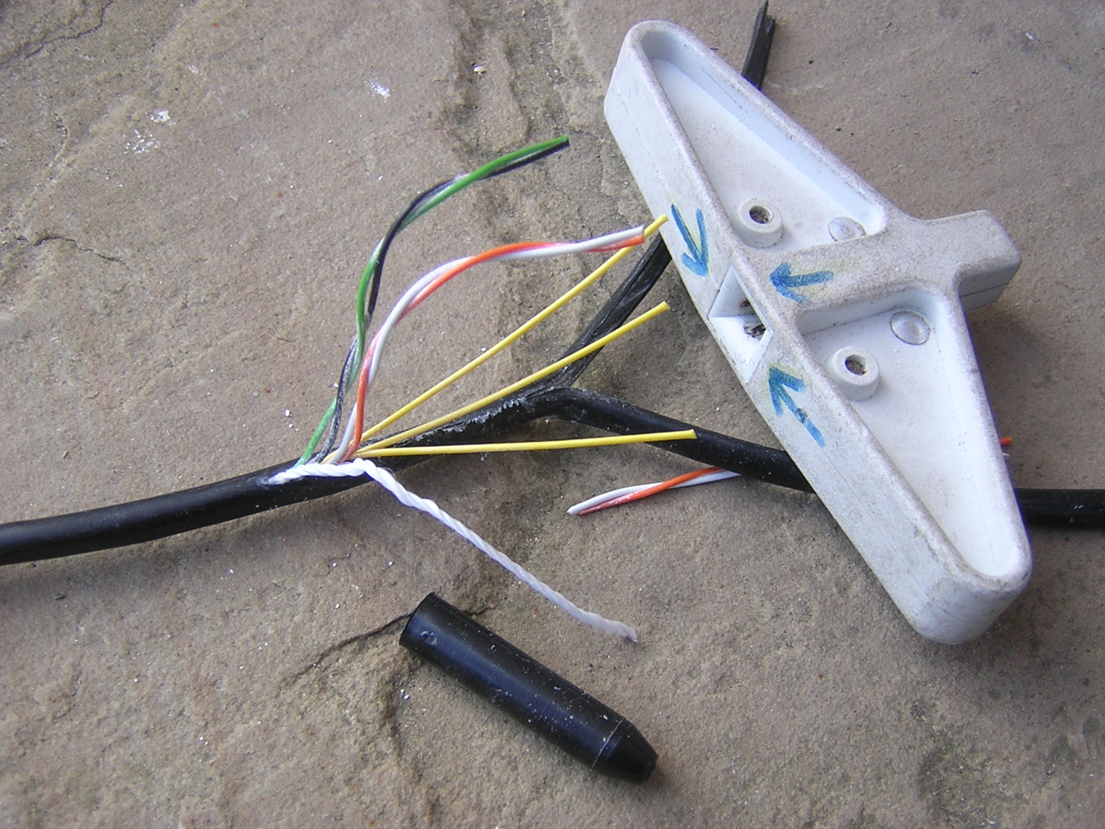
Instructions on how to connect home telephone wiring to. Fitting a nte5 master socket direct to the drop wire.

Gd 8027 Telephone Box Wiring Furthermore Phone Wall Plate
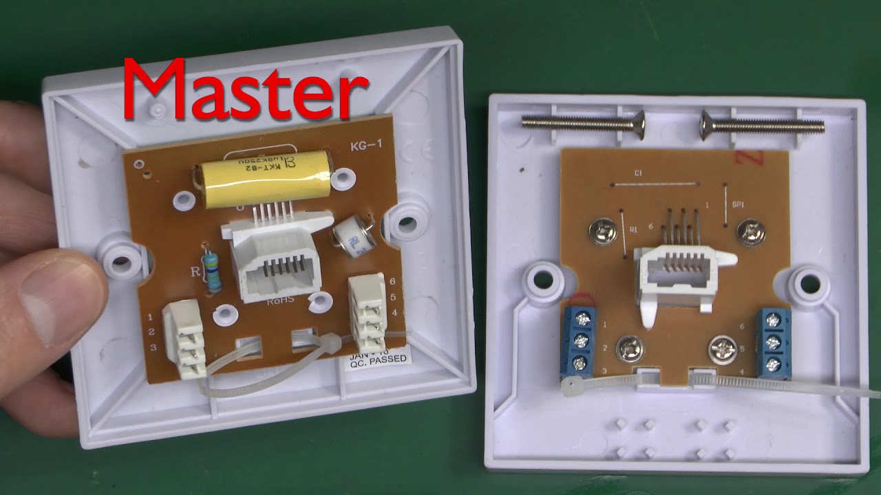
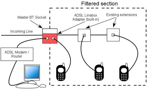
Nte5 master socket wiring diagram. Hi this video is a very quick example of how to wire up a nte5 master socket as found in the uk on bt and virgin media telephone lines. The following guide covers the nte5cvdsl mk4 combination socket available here. Terminal pins 1 and 6 may be absent on some versions of cnte5 but these connections are not normally used anyway. Failing to do so will open the blades permanently damaging the connector. C1 18μf capacitor r1 470kω out of service resistor r2 bell wire resistorchoke colouring says ω meter reads 77ω inside the nte5c telephone master socket 5c. In recent years nte5 or cte5 lineboxes are fitted in place of master sockets these have a removable lower half panel which house the terminals to connect wiring to the secondary sockets.
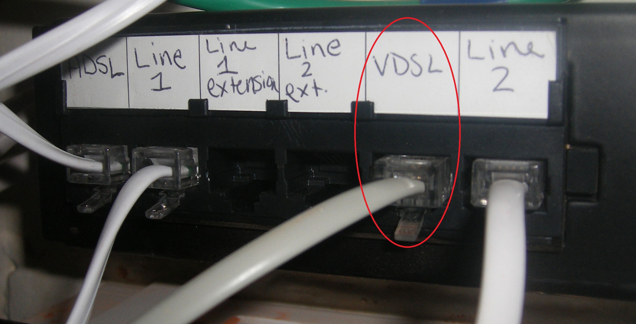
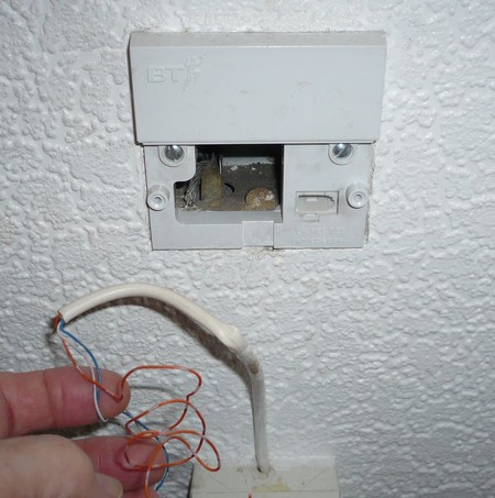
Components from left to right. Hi i have a 5c master socket. Please note as soon as either the original lower front plate or a mk4 faceplate is removed from the nte5c master socket any extension wiring connected to the nte5c backplate the part with the test socket is also disconnected. I added an extension to the master socket blue with white rings to 2 orange with white rings to 3 and white with blue rings to 5. In home wiring and test socket 1. A circuit diagram of the bt openreach nte5c telephone master socket.
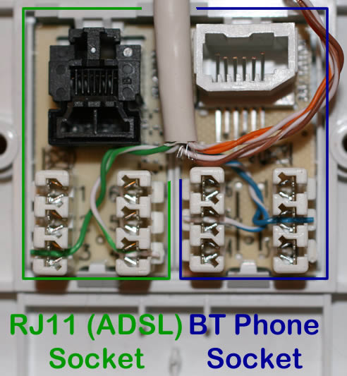
Telephone wiring colour code bt nte5 master socket. Black wire connected to a and green wire connected to b. The connections on the mk4nte5c are cam lock connectors do not require a tool. Hi there im in need of some help. With the mk4 vdsl filter front cover removed the test socket can be seen at the centre top of the back plate and instructions on how it is used are shown above. 4 feb 2011 messages.
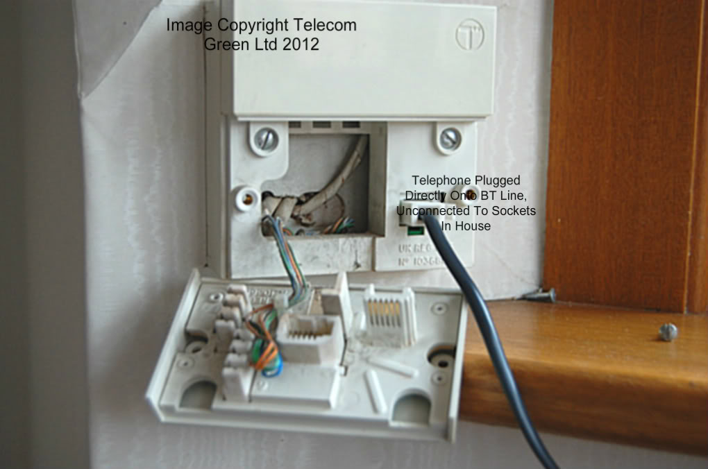
The following pictures show the standard bt telephone wiring colour code used with the bt nte5 master socket. Please note you must use the correct inserter tool to push the wires in to the phone socket idc connectors. There are no other nte5 sockets in the house which is why i suspected as you do that the wiring looks a bit odd. Also the wiring setup does not match anything ive seen in other diagrams and pictures that ive googled which is wht im a little perplexed. For much more detail then please watch my longer 22 minute. The phone works fine when plugged in to the test socket.
R1 service resistor r2 bell wire resistor c. The back plate is the same as the nte5c. Page 1 of 2 1 2 next charliemcc. Discussion in alarms cctv telephones started by charliemcc 5 feb 2011.
Gallery of Nte5 Master Socket Wiring Diagram