This is the wiring diagram for the pac tr 7 universal trigger output module video bypass. This frequency is in 8 khz range.
High Quality Car Power Supply Audio Adapter Noise
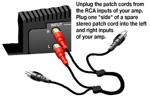
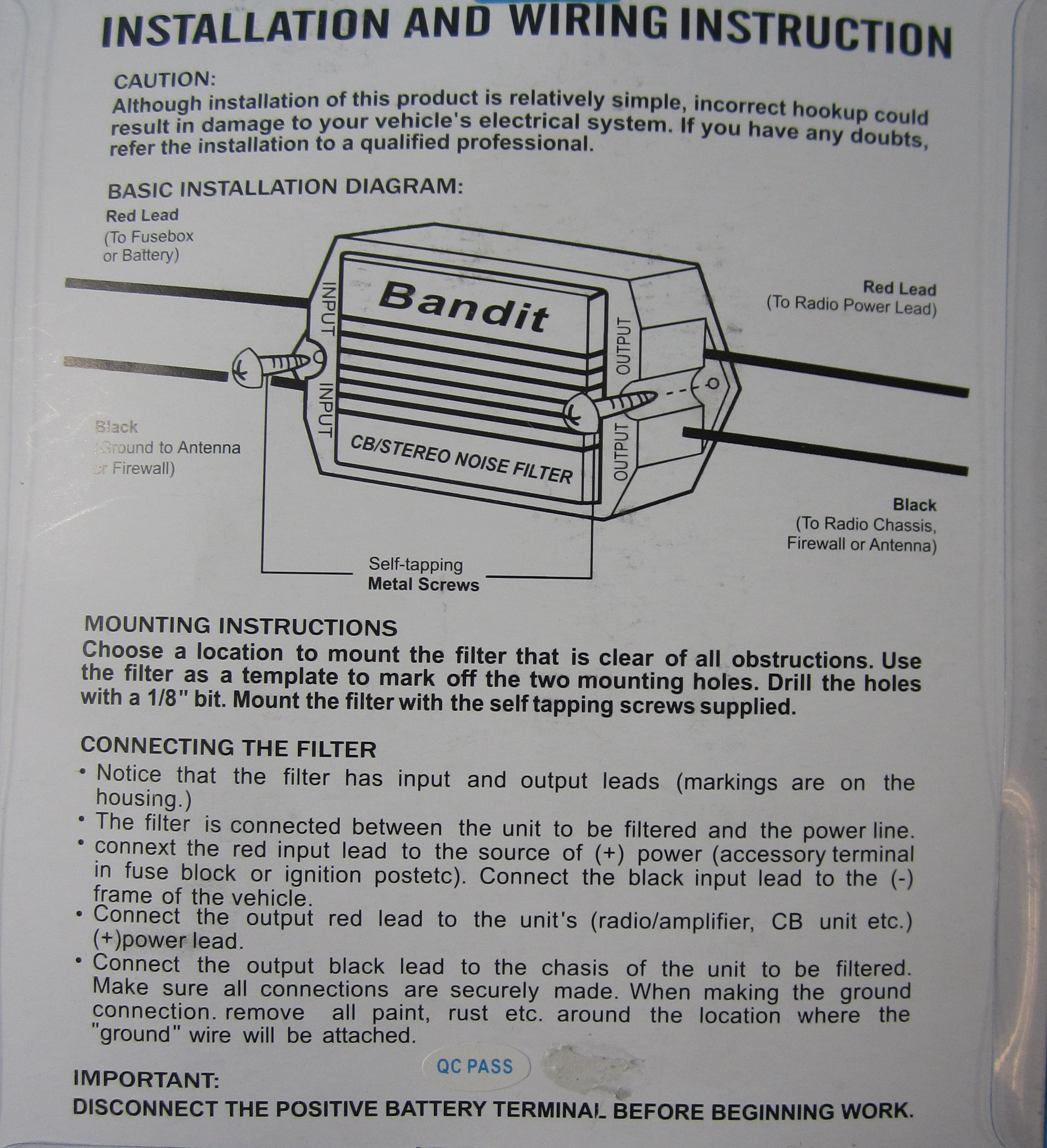
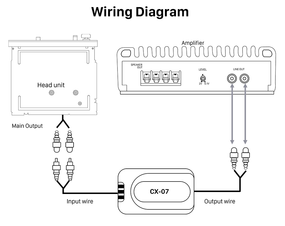
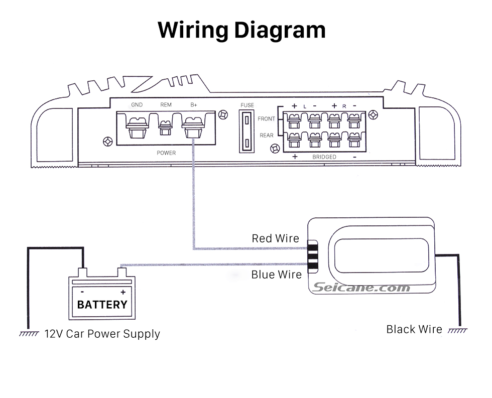
Noise filter wiring diagram. Seems like bad planning since there are red and yellow power wires involved in a car stereo. I just bought the pac sni 1 rca noise filter for my amplifier. Figure 1 noise filter for stereo system. The magneto filter is faa pma approved and is compatible with the bendix series s20 s21 s200 d3000 d4000 magneto. Ive been having a lot the instructions say. The sni 1 is of the sni connect the brown wires to ground only if there is no sound out of the amplifier.
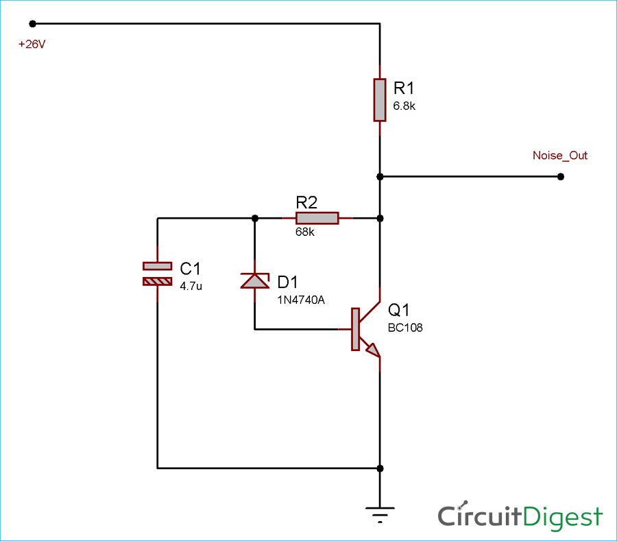
This filter has been used by avionics shops oem aircraft manufacturers and fbos to attenuate and suppress pulsating noise generated by their aircrafts magneto systems. These convert the high level. If the noise causing accessory has a motor a source noise filter can be installed on the accessorys power lead to minimize radiated noise. As early as. Mobile mount electronic noise filters operate on 6v dc to 48v dc the interference or electronic noise generated by alternators ignition systems motors etc can render a vehicles radio data receivers or other electronic equipment virtually useless. Figure 1 include the emitter common follower output circuit in series cascade in each channel.
It says ck nsfl2 20 amp noise filter and it has a red wire on one side yellow wire and ground wire on the other side. Make the noise that change this circuit goes to are left a little for power supply source should use battery 9v. Figure 1 noise filter for stereo system figure 1 includes the emitter common follower output circuit in series cascade in each channel. Subwoofer wiring wizard easy to understand diagrams of one to four speakers with a variety of single and dual voice coils. By have switch choose filter the noise. Electronic noise filters by newmar powering the network.
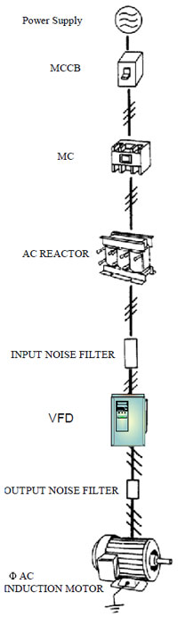
The high frequency noise in 2 channel will be refuted by through high pass filer include r3 to r7 and c3 to c5. This frequency is in 8 khz range. This interference takes the form of popping or static on radios or audio gear and. It filters unwanted signals that are lower or higher than the audio frequencies. Because will decrease the noise from power supply give with this circuit there yes. Vehicle wiring our free vehicle wiring section includes car alarm wiring remote start wiring car stereo wiring cruise control wiring navigation wiring and more for most vehicles available in the us.
A low pass filter and a high pass filter in a cascade configuration. The noise will go out while the sound still normally stereo system. I got this noise filter for my car stereo. The high frequency noise in 2 channel will be refutedby through high pass filer include r3 to r7 and c3 to c5. It has 2 filters. So my issue is a red wire on one side of the filter and a yellow on the other side.
This audio noise filter circuit is a bandpass filter for audio frequency band. If the car computer or other motor less accessory is causing the problem move your receivers wiring away from that accessory to minimize the radiated noise. By sw1 for rumble noise filter and the sw2 for scratch noise filter. Both filters are second order filters with a 24 dboctave fiter capability.
Gallery of Noise Filter Wiring Diagram