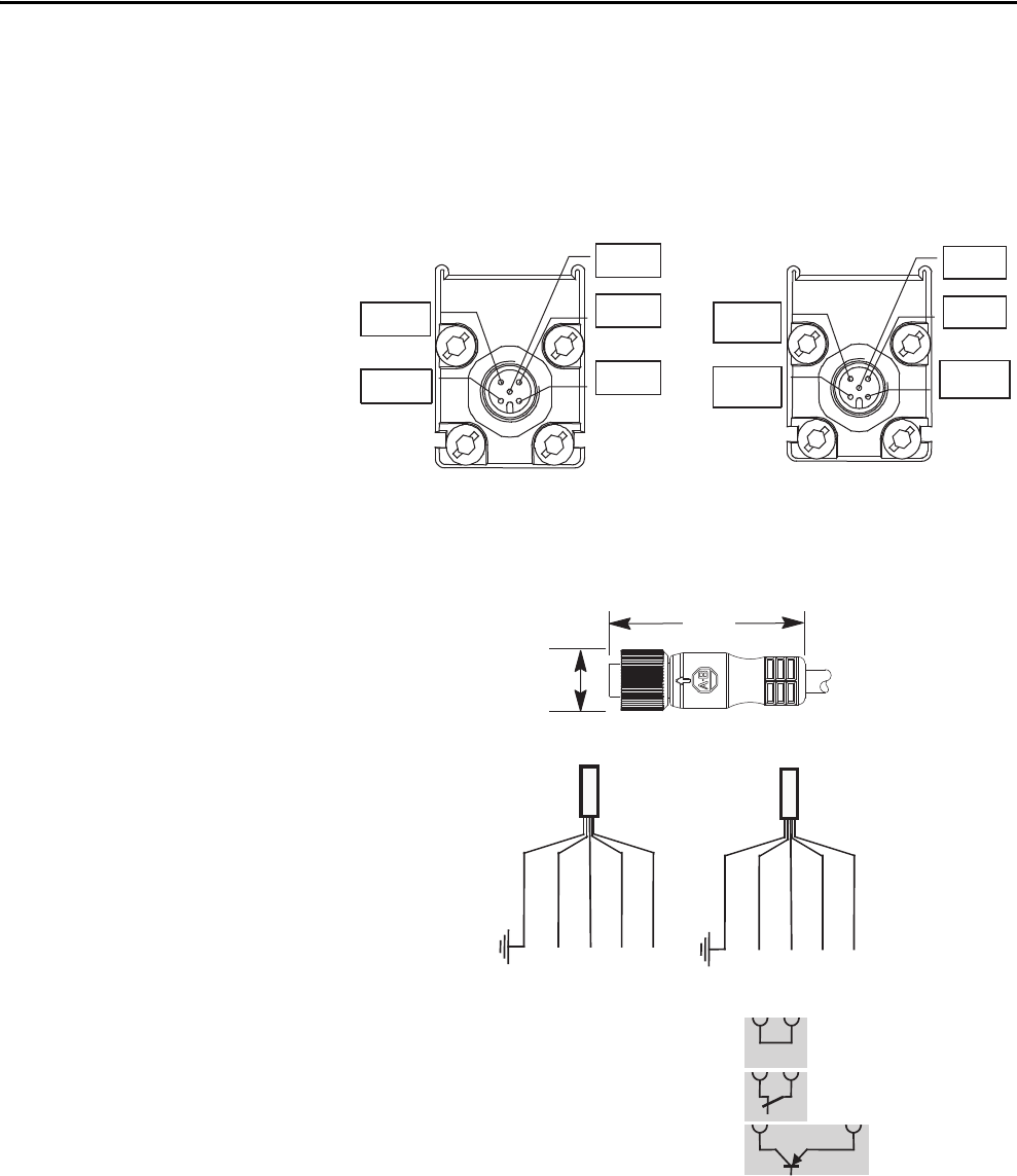
These relays are ideal for relatively small safety applications and single zone control and available in electromechanical version or solid state models for applications involving high cycle rates. Each of the recommended conversions shows the terminal locations of the old and new devices so the user can plan the conversion appropriately.

Operator Interface Cable Pull Switches Platt Com S117
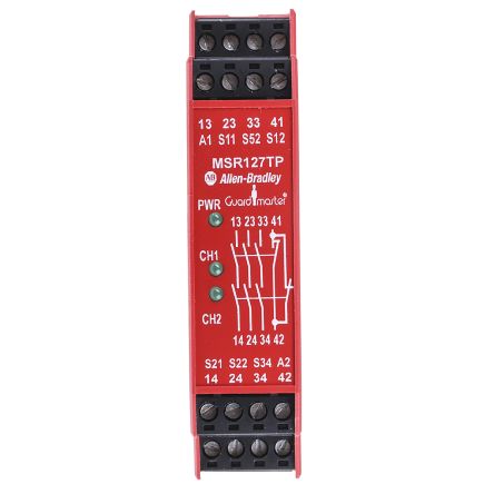
Msr127tp wiring diagram. When connected in the two normally closed fashion the msr127rtp checks for cross faults across the two inputs. One normally closed two normally closed or with two pnp connections from a light curtain. Our msr100 single function safety relays support a wide variety of input devices and output configurations. Msr127tp wiring diagram will definitely help you in increasing the efficiency of your work. Solid state auxiliary output guardmaster glt safety relay 440r gl2s2t. March 29 2019 april 12 2020.
Safety relays4 39monitoring safety relaysminotaur msr127rptpproduct selectiondimensionsmm inches block diagramtypical wiring diagramsinputssafety outputsauxiliary outputs datasheet search datasheets datasheet search site for electronic components and semiconductors integrated circuits diodes and other semiconductors. The msr127rtp can be connected in three different input wiring configurations. Guardmaster msr127tp safety relay 440r n23132 msr127rp safety monitoring relay 24v acd 440r n23135s. Msr127tp wiring diagram coleman pop up camper wiring diagram. Expansion module single wire safe is only input 1 nc. Typical wiring diagrams s11 s12s52 s21 s22 s34 a2 a1 l1 n 14 24 13 23 4133 l1 k1 l2 k2 l3 34 42 k1 k2 m light curtain 24v dc out1 out2 reset msr127rp s11 s12s52 s21 s22 s34 a2 a1 l1 n 14 24 13 23 4133 l1 k1 l2l3 34 42 k1 m e stop msr127tp light curtain monitored manual reset monitored output single channel e stop automatic reset no output.
Fashion the msr127rtp checks for cross faults across the two inputs. Literature library rockwell automation. The msr127rtp can be connected in three different input wiring configurations. When connected to light curtains the light curtain must perform the cross fault detection. Typical wiring diagrams s11 s12s52 s21 s22 s34a2 a1 l1 n 14 24 1 32 33 41 l1 k1 l2 k2 l3 3442 k1 k2 m light curtain 24v dc out1 out2 reset msr127rp s11 s12s52 s21 s22 s34a2 a1 l1 n 14 24 13 23 33 41 l1 k1 l2l3 3442 k1 m e stop msr127tp light curtain monitored manual reset monitored output single channel e stop automatic reset no output. 440r single function safety relays 1 nc.
1 nc 2 nc or with 2 pnp connections from a light curtain. Wiring terminal locations moving a wire from the top of the old device to the bottom of the new device in a control panel cannot be taken lightly. When connected in the 2 nc.
Gallery of Msr127tp Wiring Diagram