Figure 8 2 wire rtd wiring minco tel. Ct224 software instructions ct224.

32 Heat Trace Wiring Diagram Wiring Diagram List
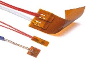
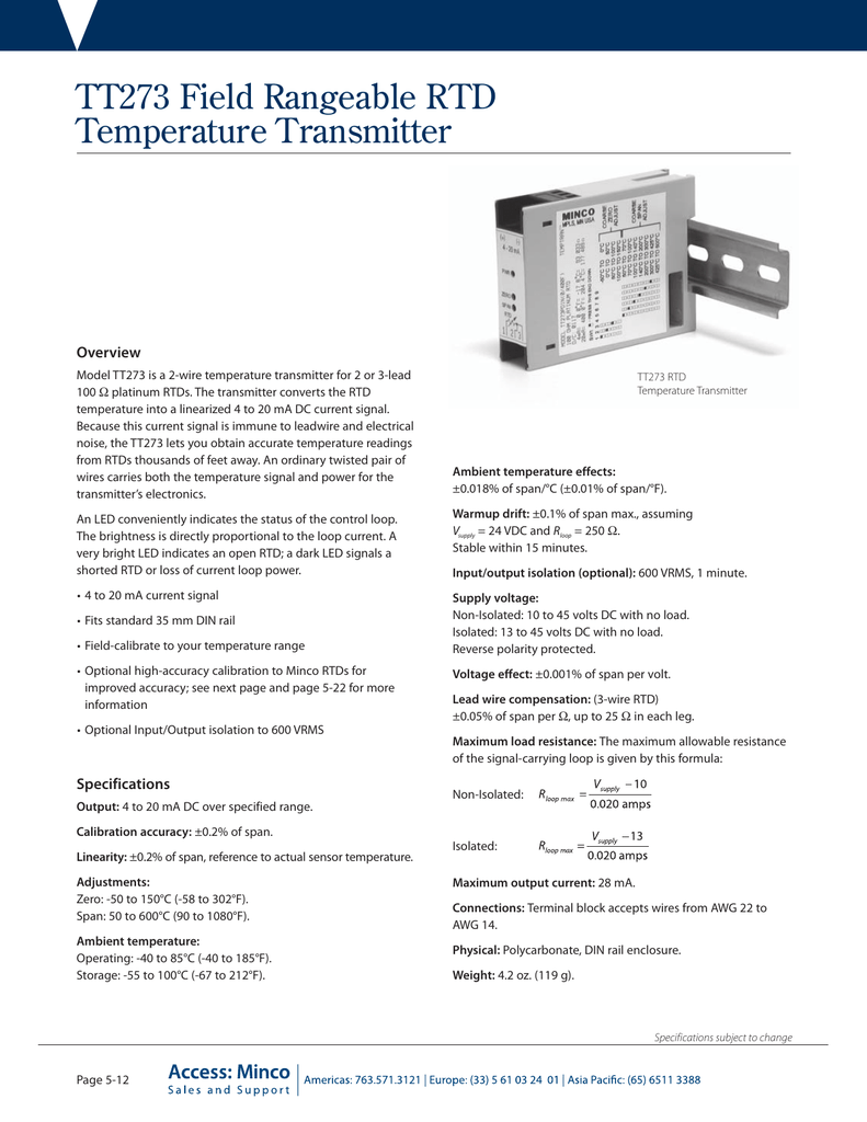
Minco rtd wiring diagram. They feature 3 per element lead wires of stranded copper with ptfe insulation available in a variety of standard lengths and thicknesses. Mincos temptran rtd transmitters provide a 4 to 20 ma signal or hart protocol that can be sent over long distances with a simple 2 wire system. The model tt176 is a 2 wire temperature transmitter for 2 or 3 lead 100 ohm platinum or 3 lead 10 ohm copper rtds. Minco launches new flex circuit design guide. Well be using 1 platinum series meter pr11 probe a d20 meter with an omega calibrator to see if our rtds are reading. Minco medical applications guide minco solutions are being used in a variety of applications to meet the.
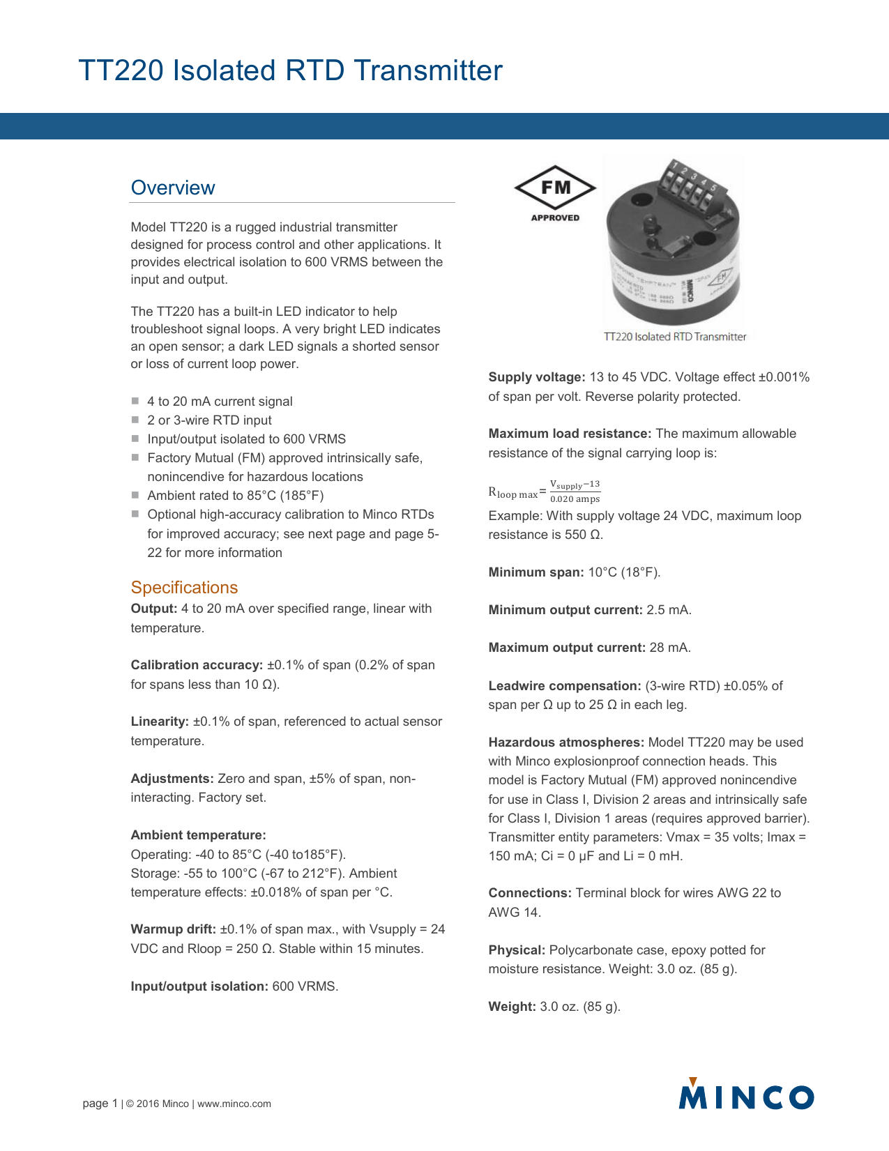
Because this current signal is immune to leadwire and electrical noise the tt176 lets you obtain accurate temperature readings from rtds. Tt859 temptran 2 wire temperature transmitter for rtd thermometers installation and operating. Reliable and continuous monitoring. The transmitter converts the rtds temperature into a linearized 4 to 20 ma dc current signal. Here are tips how to wire your rtd to a meter by omega engineer chet. The ultimate heater control and prototyping solution.
Minco part numbers decoded. Special high accuracy calibrationfor high system accuracy specify transmitters with matched calibration. 763 571 3121 fax. Back to frequently asked questions. 763 571 0927 intrinsically safe non incendive. Rtds resistance temperature detectors are offered with 2 3 or 4 lead configuration.
Minco dual element rtds match most instrumentation. Voltage 35 vdc. These class h rtds feature a high temperature epoxy glass body. High school students turn to thermal clear minco updates as9100 certification. Minco glossary of terms. For models tt176 and tt676 the temptran has been factory calibrated for its marked temperature range or else for a specific rtd.
7300 commerce lane minneapolis mn 55432 3177 usa. Ct325 temperature controller ac wiring diagram external ac ssr wiring diagram. Replacing a wire harness with a flex circuit. Minco tt210 tt211 tt710 and tt711 2 wire temperature transmitters installation and operating instructions tt211 tt711 tt210 tt710 minco products inc. Do not change its zero and span adjustments. The rtd connections for the temptran in the wiring diagram below must be connected as shown or the transmitter will not function properly.
The best configuration for a specific application depends on a number of factors however the sensor configuration must match instrumentation otherwise leadwire resistance cancelation circuitry may be ineffective. See section 4 for complete temperature transmitter specifications.
Gallery of Minco Rtd Wiring Diagram