Real time clock and timed functions. The following figure shows the vertical e bypass wiring connection points.

Powerflex 4 Vfd Connection Diagram Diagram Base Website
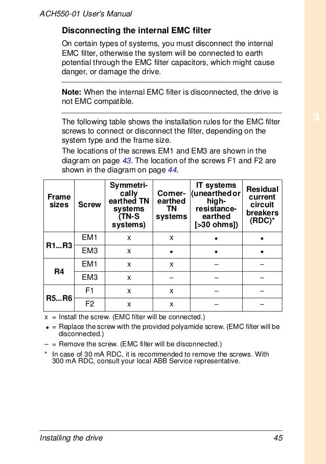
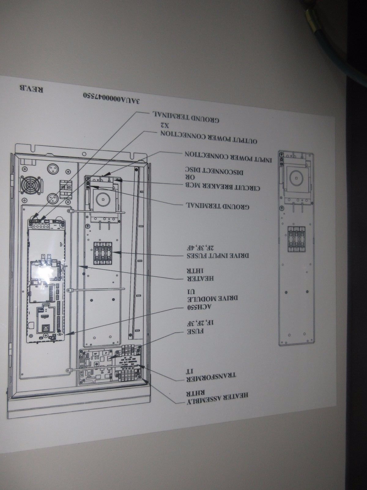
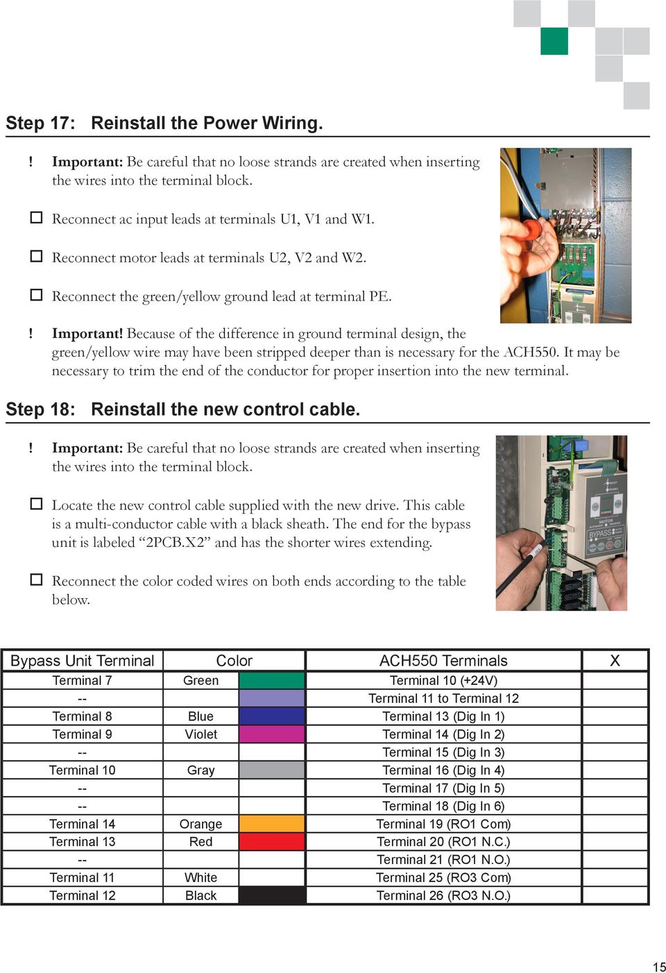
Abb ach550 control wiring diagram. Collection of abb ach550 wiring diagram. Connection diagrams vertical e bypass ach550 vertical e bypass units are configured for wiring access from the bottom only. Refer to the ach550 uh users manual for control connections to the drive. Preparing for installation 3. The ach550 must be installed by a competent person. Conduit kit wiring r1r6 drives with the ul type 1 enclosure requires a conduit kit with the following items.
Interconnecting wire paths may be revealed about where particular receptacles or fixtures should get on a common circuit. Contents of this manual 2. Installing the drive 4. Abb ach550 wiring diagram building circuitry representations show the approximate places and also interconnections of receptacles illumination and also irreversible electrical services in a structure. Conduit box screws cover. Bp0054 ach550 e bypass control board terminals x2 disconnect switch.
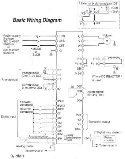
A wiring diagram is a simplified conventional photographic representation of an electric circuit. Abb ach550 wiring diagram abb vfd control wiring diagram additionally air conditioning wire rh ayseesra co abb 150 wiring. Start up and control panel 5. Application macros and wiring 6. If in doubt contact your local abb sales or service office. Ensure the motor is compatible for use with the ach550.
It shows the parts of the circuit as streamlined forms and the power and also signal links in between the tools.
Gallery of Abb Ach550 Control Wiring Diagram