Cable with a braided screen is to be preferred for flexible interconnections while foil screened cable provides good screening and is recommended for permanent wiringlapped screen cable is not recommended as it provides inferior screening at high frequencies and is often. This articles is part of my ongoing series on desktop electronic music dem.

Midi Transcoder Schematics
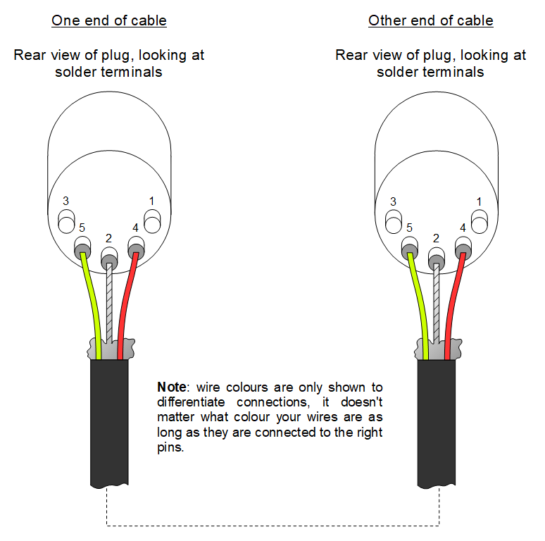
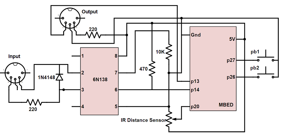
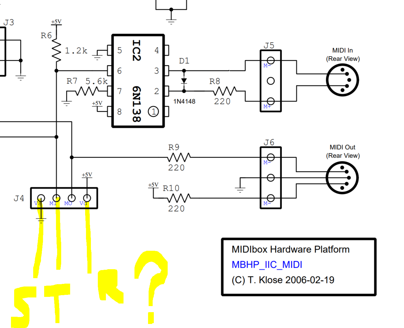
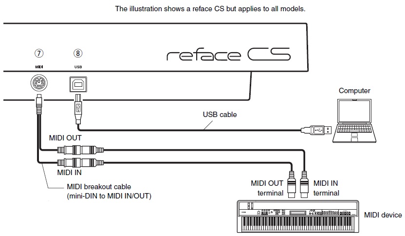
Midi wiring diagram. The cable for midi should be screened twisted pair. Midi d auto 1991. Leads direct sell and manufacture cables using a wide range of din standard connectors which you can view and purchase the most common of these are midi and keyboard and mouse. 2 5 pin din female jacks 3 220 ohm resistors 1 270 ohm resistor 1 10 kohm resistor 1 in914 diode 1 2n2222 npn transistor 1 6n138 optoisolator 1 7404 hex inverter. The original circuit diagram is shown below for reference it is the most common circuit in use today and is still acceptable. Midi d system 1990.
The joystick connector is found on sound cards. Of course the 15 pin joystick plug has disappeared and joysticks now connect via usb. The hardware required for this. Midi d auto manual pt1 midi d auto manual pt2 midi d auto wiring diagram. Original electrical specification diagram note. This article will explain how midi cables are wired starting with conventional din 5 sockets then looking at trs connectors.
The midi port used with personal computers when found on sound cards uses a 15pin d connector the 15 pin midi connector has the following pin out. The maximum length of a standard midi cable is given as 15m 50 ft. Demo distiller manual demo distiller wiring diagram. Midi d system manual midi d system single microswitch wiring diagram midi d system double microswitch wiring diagram. This will help anyone who needs to trouble shoot wiring or solder their own cables. Midi has grown up alongside the personal computer and pcs frequently feature midi interfaces.
Midi was hidden in the 15 pin joystick interface on older pc soundcards broken out to 5 pin din connectors with a pigtail adapter. There is a specific wiring schematic for midi input and outputs as follows. Din midi wiring this page gives information on wiring various din connectors for various purposes including midi musical instrument digital interface connections. For more details please see the complete midi 10 detailed specification. This diagram is superceded by midi 10 electrical specification update 2014. Ic circuitry for the midi in midi thru and midi out interfaces.
There really is no 15 pin d defined in the current motherboard standards used as a game port. The landing page provides easy access.
Gallery of Midi Wiring Diagram