Map sensor wiring diagram part 1 note. The following tutorial may be of help when testing the actual map sensor to see if its creating a signal or not with a multimeter.
1996 1998 Map Sensor Circuit Diagram 2 0l Neon
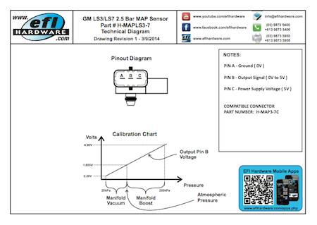
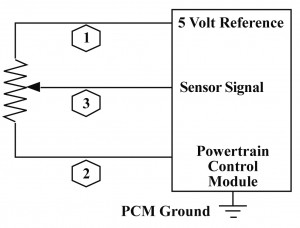
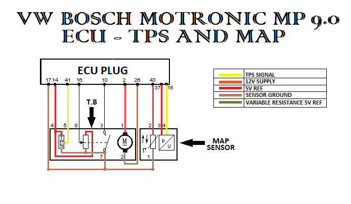
Map sensor wiring diagram. I know that some sensors werent grounded according to the diagrams but that actually you had 0v between one of their pin and the ground. Stock top locking tab up wires facing you. Wire up aem bar map sensornismotronicsa help map sensor installation. Pin 3 ground orange. Pin 1 5v ref grey. Manifold absolute pressure map sensor wiring diagram.
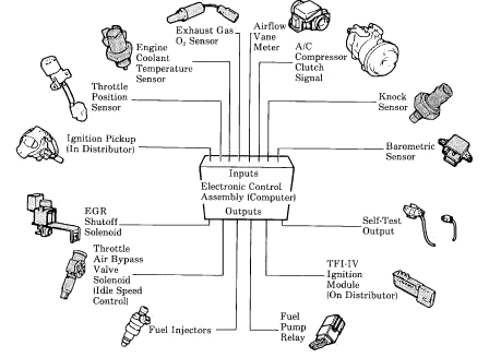
This sensor detect the intake manifold pressure change value and converts it into a signal voltage. Tps testingsee figures 2 3 and 4. The manifold absolute pressure map sensor wiring diagrams and info in this page apply only to 1996 1997 1998 dodge ram pickups vans and dakota with a 39l 52l or 59l gasoline engine that use the 3 connector pcm. Get the scoop on the map sensor from an electronic point of view and towards reading wiring. Map wiring diagram here need a bit of help maybe you should measure the voltage between each of the two pins and the ground. Map sensor pin swap.
Im also replacing my intake air temp sensor with a delco sensor and connect the wires coming from the delco iat sensor to the wiring of the maf sensor since it has a built in iat sensor. Pin 2 signal green. Video sharing camera phone video phone free upload. Map sensor wiring diagram. Mass air flow sensor electrical connections theory and troubleshooting from wiring diagram duration. A map sensor has 3 wires ground 5v source and signaldiy.
Wire installation car fix engine repair buggy car hacks diy electronics electric cars planer cars. Automotive electronics from schematics by joseph 1231 views 842. Probe the terminals of the map sensor to check for proper reference voltage. Backprobe with a high impedance voltmeter at tps terminals a and b. Anyone know the wire config of the maf sensor. Map and maf sensor wiring diagram ill use a stand alone ecu for my 07 eurodm sti.
Location of the map sensor tbi system shown. The aem map sensors have threaded ends on them and can be installed directly into the intake manifold after it has been drilledtapped to accept the sensor. Sloppy mechanics wiki gm map sensor identification map sensor wiring diagram gm map sensor identification information 1 bar 2 bar 3 bar maf sensor wiring diagrams wire harness installation instructions painless wiring a simple map maf enhancer fuelsaver mpg inc wiring and sensors megamanual wiring diagrams ertyu ls series.
Gallery of Map Sensor Wiring Diagram