Loop Wiring Diagram Instrumentation Pdf

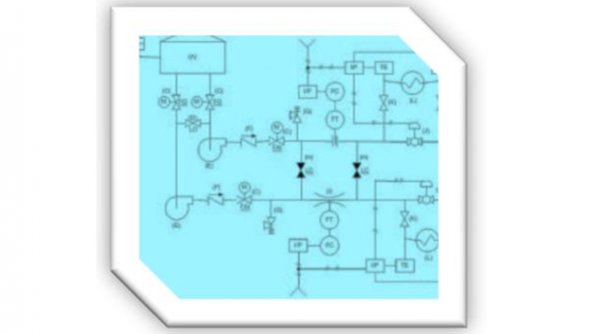
2 word description of loop functions within the title. Pids and loop diagrams pids and loop diagrams are construction and documentation drawings that depict the flow of the process and illustrate the instrumentation control and measurement interactions wiring and connections to the process.

Piping And Instrumentation Diagram Wikipedia

Piping And Instrumentation Diagram Wikipedia

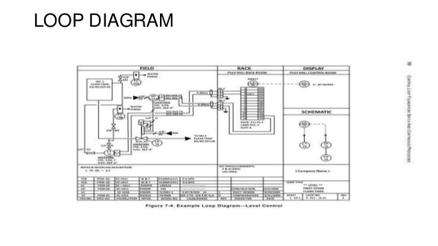
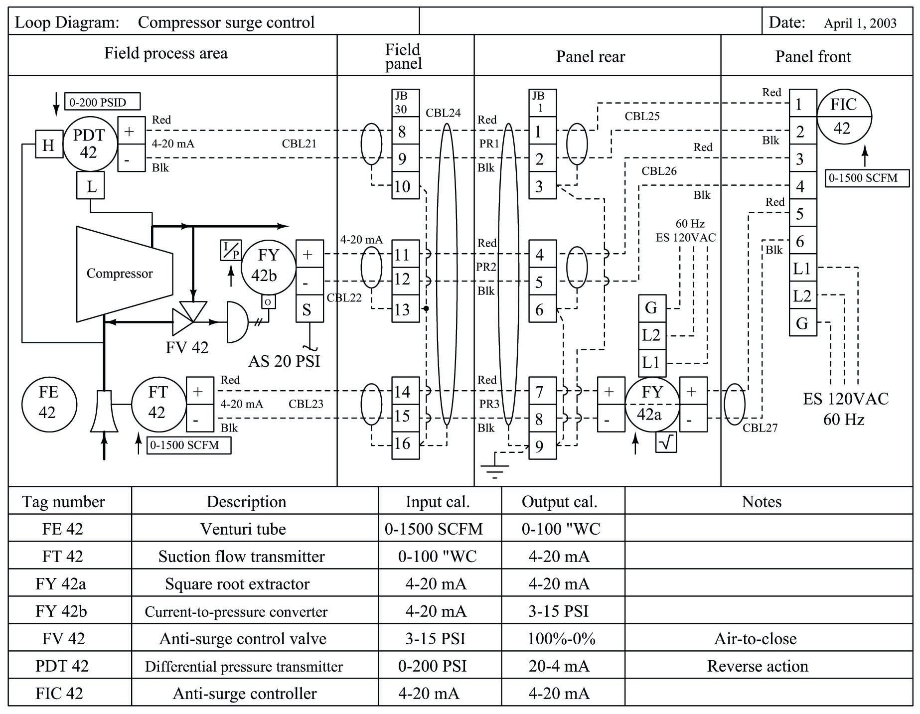
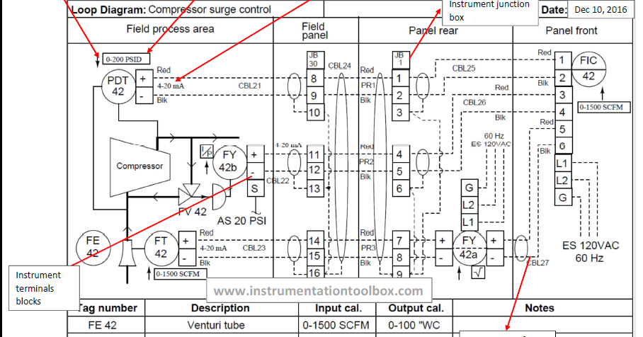
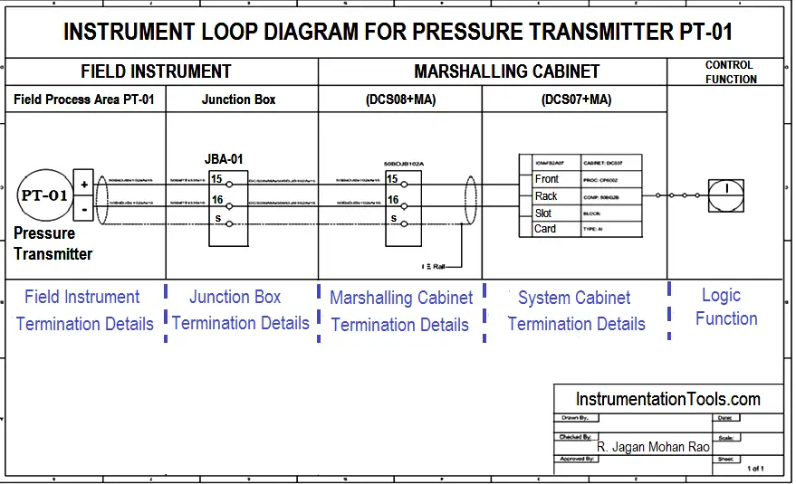
Loop wiring diagram instrumentation pdf. Other principal components of the loop to be shown and identified under isa s51 instrumentation symbols and identification. 1 identification of the loop and loop components shown on the pids. As a minimum an instrument loop diagram shall contain the information covered below. These set of drawings are more detailed than process and instrument diagrams pids. A loop diagram will. 1 identification of the loop and loop components shown on the pids.

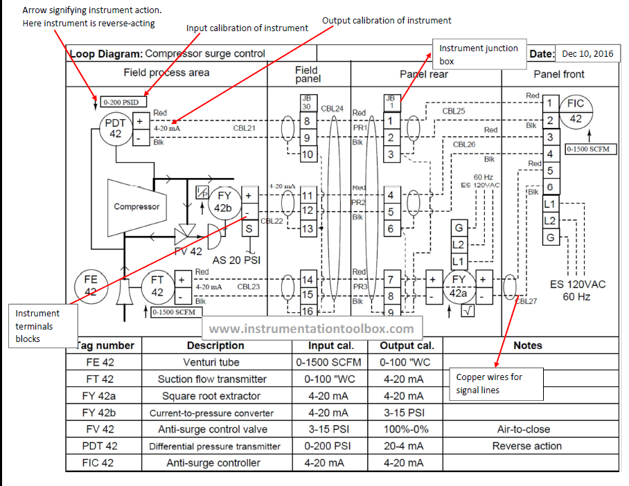
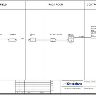
Instrument loop diagrams are also called instrument loop drawings or loop sheets. The only type of diagram for this system more detailed than a loop diagram would be an electronic schematic diagram for an individual instrument which of course would only show details pertaining to that one instrument. Loop wiring diagram instrumentation pdf wiring diagram is a simplified tolerable pictorial representation of an electrical circuit. Loop diagrams are the most detailed form of diagrams for a control system and thus it must contain all details omitted by pfds and pids alike. It shows the components of the circuit as simplified shapes and the facility and signal links amongst the devices. As a minimum an instrument loop diagram shall contain the information covered below.

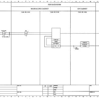
The process is illustrated in sections or subsystems of the process called loops. Other principal components of the loop to be shown and identified under isa 51 instrumentation symbols and identification. 2 word description of loop functions within the title. Thus the loop diagram is the most detailed form of diagram for a control system as a whole and as such it must contain all. Wiring diagrams of plc and dcs systems di do ai ao x liquid level control using flow loop control systems since liquid level can only change in a vessel if there is an imbalance of inlet and outlet flow rates would this system be practical to achieve stea.

Gallery of Loop Wiring Diagram Instrumentation Pdf

Pressure Instrumentation
Download Now
Pressure Instrumentation
7 Best Piping And Instrumentation Diagram Images Piping And
Download Now
7 Best Piping And Instrumentation Diagram Images Piping And
13 Best Instrumentation Images Piping And Instrumentation
Download Now
13 Best Instrumentation Images Piping And Instrumentation
Learn How To Read P Amp Id Drawings A Complete Guide
Download Now
Learn How To Read P Amp Id Drawings A Complete Guide
Basics Of Instrument Loop Diagrams Learning Instrumentation
Download Now
Basics Of Instrument Loop Diagrams Learning Instrumentation
Current Loop Wikipedia
Download Now
Current Loop Wikipedia
Fundamentals Of Instrumentation Process Control Plcs And
Download Now
Fundamentals Of Instrumentation Process Control Plcs And
Analog Output 4 20ma Complete Loop Drawing From Dcs To Field Instrument Guru
Download Now
Analog Output 4 20ma Complete Loop Drawing From Dcs To Field Instrument Guru
Wiring Diagram And Loop Drawing Conversion For Spi
Download Now
Wiring Diagram And Loop Drawing Conversion For Spi
Loop Diagrams Loop Sheets Control And Instrumentation
Download Now
Loop Diagrams Loop Sheets Control And Instrumentation
Single Line Electrical Diagrams Electric Power Measurement
Download Now
Single Line Electrical Diagrams Electric Power Measurement
Basics Of Instrument Loop Diagrams Learning Instrumentation
Download Now
Basics Of Instrument Loop Diagrams Learning Instrumentation
Interpreting Piping And Instrumentation Diagrams Symbology
Download Now
Interpreting Piping And Instrumentation Diagrams Symbology
Piping And Instrumentation Diagram P Amp Id Piping And
Download Now
Piping And Instrumentation Diagram P Amp Id Piping And
How To Create Instrument Loop Diagram Marshalling Loop
Download Now
How To Create Instrument Loop Diagram Marshalling Loop
Lead Compensation Techniques For Rtds
Download Now
Lead Compensation Techniques For Rtds
Five Terms You Must Be Familiar With Scada Dcs Plc Rtu
Download Now
Five Terms You Must Be Familiar With Scada Dcs Plc Rtu
Pressure Transducer Transmitter Or Sensor The Design
Download Now
Pressure Transducer Transmitter Or Sensor The Design
Wiring Diagram And Loop Drawing Conversion For Spi
Download Now
Wiring Diagram And Loop Drawing Conversion For Spi