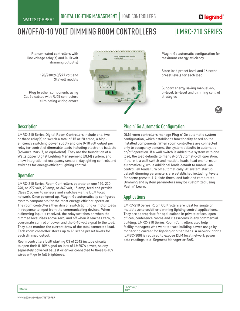
All line voltage wiring is 12 awg. Manufacturer lmrc 213 additional features plenum rated controllers with line voltage relays and 0 10 volt dimming outputs.

2010 Dlm Solution Legrand
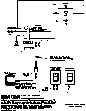
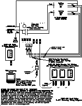
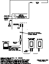
Lmrc 213 wiring diagram. Depending on outputs used a 4 square extension box may be needed. For dimming ballasts or drivers connect the 0 10v control wires to the 0 10v terminals that match the load relay output connection. Lmrc 222 75 c copper wire only santa clara ca 8008798585 industrial control equipment 46a9 indoor use only mounting the controller the room controller mounts to a four square deep junction box using the included mounting plate with the hinge pins extending away from the box as shown. Terminate wiring according to wiring diagram. The lmrc 211 is rated for up to 20a. Plug dlm local network components together in any configuration using.
Total load rating mount to 4 x 4 x 2 18 deep electri cal box. Terminate wiring according to wiring diagram. Class 2 0 10 volt control wiring. Do not connect different load types to the relay. Plug n go automatic configuration composition 2 channel series lmrc 210 switch style digital onoff voltage rating 120277v eccn ear99. Dlm switch assignment 4 lmdm 101 rockers to wattstopper lmrc 213 room controller 0 10v dimming duration.
Cat 5e cables with rj45 connectors. The next highest serial number would have load 3 and load 4 and so forth. The lmrc 211 347 is rated for up to 15a. The aatt channel 5004 views. The low voltage lmrj cables can connect to any dlm device with an open rj45 receptacle. All line voltage wiring is 12 awg.
Connect to single 20a circuit. In a dlm local network with only lmrc 212 or lmrc 212 347 room controllers the room controller with the highest serial number is the master carrying load 1 and load 2. The lmrc 213 communicates to all other dlm devices connected to the dlm local network. Each relay is rated for up to 20a. Lmrc 212 and the lmrc 212 347 room controllers each have two load relays. Lmrc 221 75 c copper wire only santa clara ca 8008798585 industrial control equipment 46a9 indoor use only mounting the controller the room controller mounts to a four square deep junction box using the included mounting plate with the hinge pins extending away from the box as shown.
Connections shown are for example only. 90 135 lmrc 213 three relay wiring diagram pdf 6563kb 90 131 lmrc 211 one relay wiring diagram pdf 5313kb 90 231 lmrc 213 three relay with 0 10v dimming wiring diagram. Wattstopper lmrc 213 digital room controller dimmer triple digital room controller 120277v 20a 1hp class 2 triple relay onoff dimmer color. Total load for lmrc 213 not to exceed 20a.
Gallery of Lmrc 213 Wiring Diagram