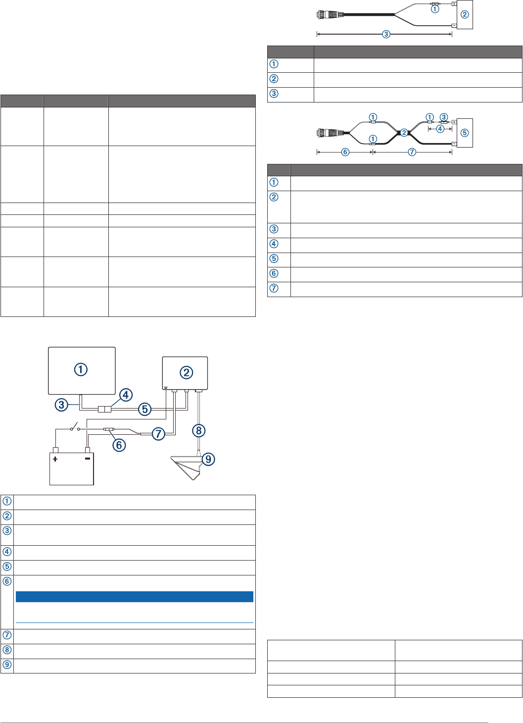
Of the positive wire on the other end this includes the inline fuse and then connects to the battery. Using the included hex wrench insert the m6 screws and attach the shaft trolling bracket to the transducer bracket.
Garmin 010 01903 01 Echomap Plus 97sv 9 Chirp Fish Finder Chartplotter With Clearvu Sidevu Transducer Canada Lakevu G3 Charts
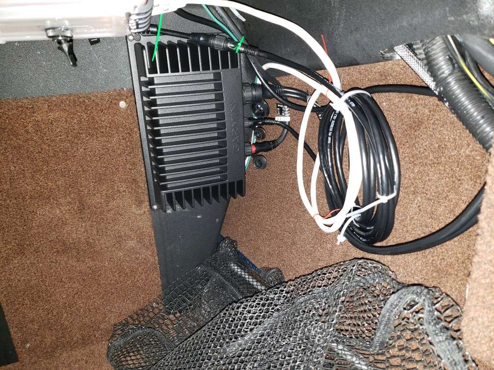
Livescope wiring diagram. Garmin livescope installation diagram. It is not numbered as it is not necessary to ground the module. See links below items in this video. Garmin panoptix livescope. Mounting the sonar module installation diagram mounting the panoptix livescope gls 10 device notice if you are mounting the device in fiberglass when drilling the pilot holes it is recommended to use a countersink bit to drill a clearance counterbore through only the top gel coat layer. I also show a diagram of all the connections you need to make to complete the.
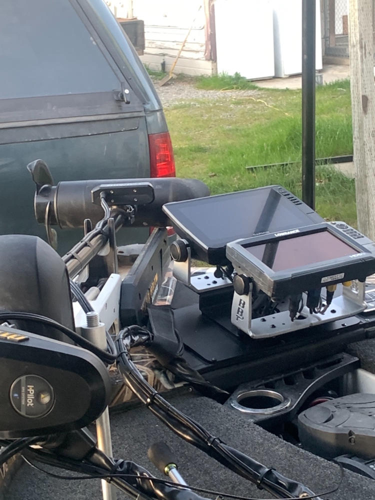
In this episode i unbox a garmin panoptix livescope and walk you through the install process in my ranger mpv 1652. You should mount the transducer as far from the motor as possible. The ground wire does not need to be 10 8 or even 6 awg wire if you do run the ground. This will help to avoid cracking in the gel coat layer. Cable wire or the cable jacket can cause transducer failure. A drawing in the instructions appears to indicate i should cut the garmin power cable splicing 8 in.
The ground wire is not numbered. Livescope wiring how to will need to splice in 15 ft. You should use the included rubber insert on a 25 mm 1 in trolling motor shaft. Of the connector end that connects to black box to my wire and spice in 8 in. Only when you are receiving rfi radio frequency interference then will you run the ground as a solution. This video explains in detail how to wire the garmin panoptix livescope black box and transducer to a garmin echomap plus 94sv.
Gallery of Livescope Wiring Diagram