Theory and operation of the jake brake engine brake duration. Engine brake maintenance 8 theory of operation 8 solenoid valve 9 control valve 9 auto lash adjusting screw 10 slave piston 10 master piston 11.

Cat Diesel Engine Electric And Electronic Manuals
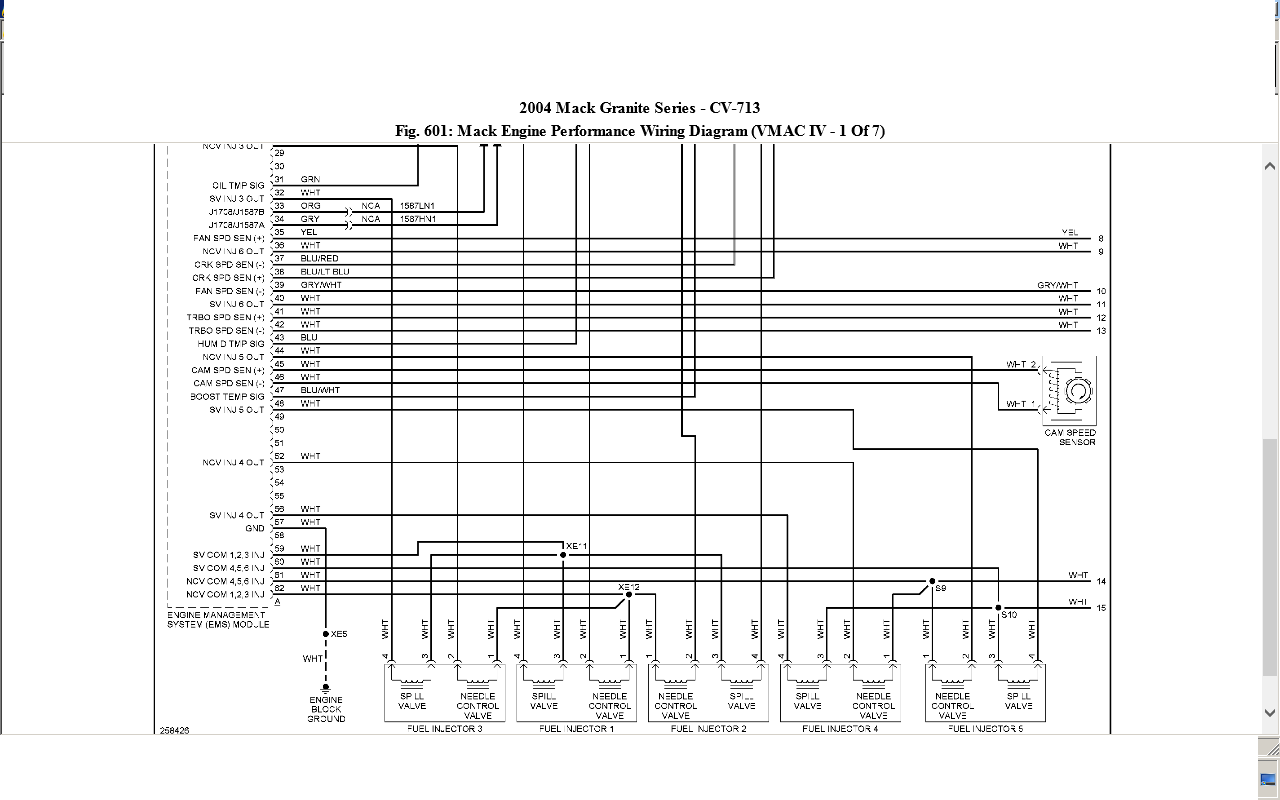
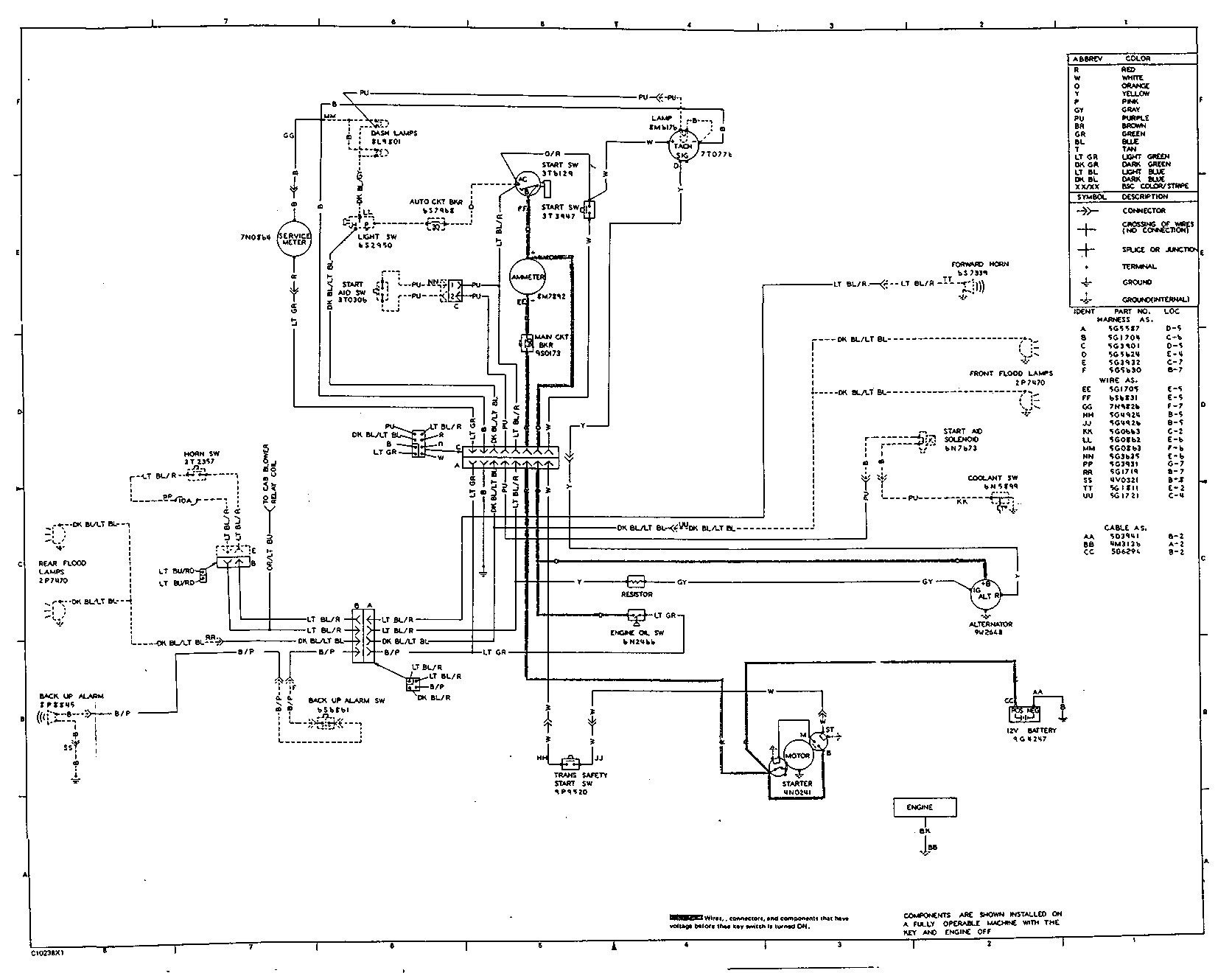
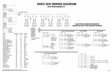
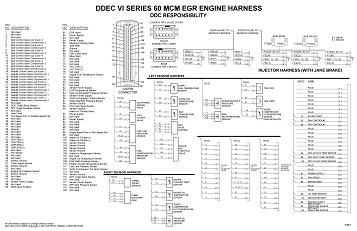
Jake brake wiring diagram. Aa spf44a spx03ea3 fb2a1 08 ag0 b a17b2 ai4 c frcj3c5 aq1 b mcsca9 f61a1 08 hb2 d a131ba4 f15a1 50 bi3 c x210aad f87 15a cust. B cat engine wiring diagram caterpillar e jake brake source co diesel diagrams fantastic starter generator custom o pin wiri all about. The model d jake brake engine retarder is designed and ap proved for use on all caterpillar and b engines. You may also use our part number cross reference tool to cross reference a specific part number or print off a complete list by manufacturer. A jake brake works by using hydraulic pressure to momentarily open the exhaust valve at the end of the compression stroke venting off the compressed air into the exhaust system. Changing brakes on a big truck.
See new video easier better. Visit howstuffworks to check out this great engine brake diagram. However i found two wires going to a black plastic box on the injection pump. Overall this requires less use of the service brakes giving them a longer life and reducing overall cost of ownership. By increasing backpressure to the engine the exhaust brake forces the pistons to push against additional force during the exhaust stroke slowing the crankshafts rotation and helping to control the vehicle speed. Hey guys i am starting to diagnose my jake brake issues.
Engine exhaust valves during engine brake operation. A b f71 15a center pin hot a b f60 30a hvac fan a b f61 5a lvd sens vendor ttu a b f76 30a 3968162 a f05 30a lecm4 b f06 20a rh sleeper pwr ports console b. The tools and wizards will help you fill in all necessary information to locate the right tune up kit and application for your trucks jake brake. Jake brake wiring diagram wiring diagram is a simplified tolerable pictorial representation of an electrical circuit. Thats where all the noise comes from. Power distribution frc 12 wiring diagram.
The braking of a jake brake occurs because of the pumping loss compressing the air and then eliminating the compressed air. Brake housing installation 5 housing placement 5 valve and injector adjustments 5 slave piston lash adjustment 6 housing wiring 7 final housing installation and test 7 chassis wiring 7 final test 7 3. Can anyone here tell me where the buffer switch would be located on this engine. It shows the components of the circuit as simplified shapes and the capacity and signal connections in the midst of the devices. Engine brake diagram this engine brake diagram outlines how engine brakes work. Wiring diagram for jakes on an 8v92.
The pictures in the downloaded pages make it look like a temp sensor almost.
Gallery of Jake Brake Wiring Diagram