The degree of protection that an internal protection device provides is classified in the iec 60034 11 standard. Assortment of iec motor starter wiring diagram.

Tesla Institute School Of Electrical Engineering
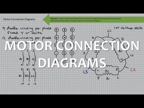
Iec motor wiring diagram. A wiring diagram is a simple visual representation from the physical connections and physical layout associated with an electrical system or circuit. Mechanical design 69 51 motor construction 70 52 frame constructions 71 53 terminal boxes 73 54 bearings. 66 412 connection diagram 68 5. The purpose of this document is to provide a simple cross reference of common schematicwiring diagram symbols used throughout various parts of the world. Always use wiring diagram supplied on motor nameplate. Iec motor starter wiring diagram what is a wiring diagram.
10 12 iec low voltage motor ranges 10 121 standard induction motors 10 122 motors for explosive atmospheres 11 123 frequency controlled motors 13 13 complete product offering. Machine tool or a simple across the line motor starter the need to recognize and understand these. Iec motor starter wiring diagram. Interconnecting cable routes may be shown about where certain receptacles or components should get on a common circuit. Iec motor starter wiring diagram architectural wiring diagrams show the approximate areas as well as interconnections of receptacles lighting and also long term electrical services in a structure. A wiring diagram is a simplified conventional photographic depiction of an electric circuit.
Tp is the abbreviation for thermal protection. Iec schematic diagrams general. It shows the elements of the circuit as streamlined forms and the power and signal connections in between the tools. Iec nomenclature 6 12 leads. Electric motor wire marking connections. The type of thermal overload for which the thermal protection is designed 1 digit.
7192018 122208 pm. Table 1 standard elementary diagram symbols 1 table 2 nema and iec terminal markings 4 table 3 nema and iec controller markings and elementary diagrams 4 table 4 control and power connections for across the line starters 600 v or less4 table 5 motor lead connections 64 table 6 enclosures for non hazardous locations 99. For specific leeson motor connections go to their website and input the leeson catalog in the review box you will find connection data dimensions name plate data etc. Different types of thermal protection exist and are identified by a tp code tpxxx which indicates. Iec motor starter wiring diagrams springer controls co.
Gallery of Iec Motor Wiring Diagram