Upon closure of the initiate switch the delay on. It shows the components of the circuit as simplified shapes and also the power and also signal links between the devices.

Read Or Download Alston With 5 Way Switch Wiring Diagram For
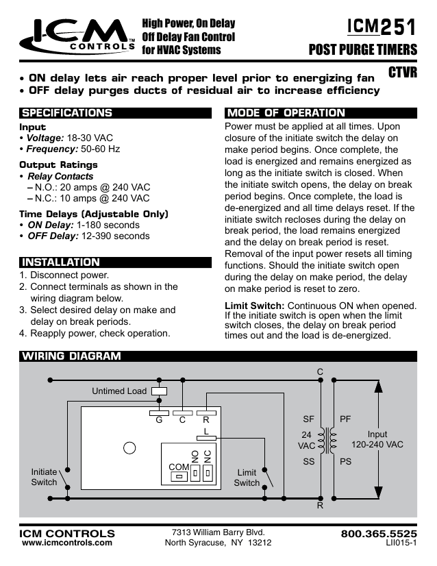
Icm251 wiring diagram. Share product dual function fan delay timer to control circulating fan in ac heat pump and forced air systems. Wiring diagram untimed load initiate switch r c limit switch pf ss ps sf 24 vac input 120 240 vac com no nc g c r l high power on delay off delay fan control for hvac systems 7313 william barry blvd. Please try again later. On delay lets air reach proper level prior to energizing fan off delay purges ducts of residual air to increase efficiency mode of operation power must be applied at all times. Collection of icm254 wiring diagram. This feature is not available right now.
High power relay output details. A wiring diagram is a simplified traditional pictorial representation of an electrical circuit. Reapply power check operation. Drives fan directly high power relay output dual function fan delay timer controls the circulating fan in heat pump ac and forced air systems off delay. Way more information than you ever wanted on how to fell a tree. Worlds best tree felling tutorial.
Guilty of treeson recommended for you. Icm251 fan blower controls. Select desired delay on make and delay on break periods.
Gallery of Icm251 Wiring Diagram