Apply the provided wiring diagram for package unit models adjacent to the wiring diagram supplied on the inside of the unit control box cover. Follow steps 1 through 4 from above.
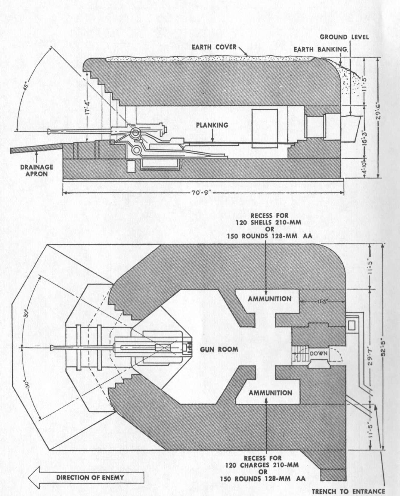
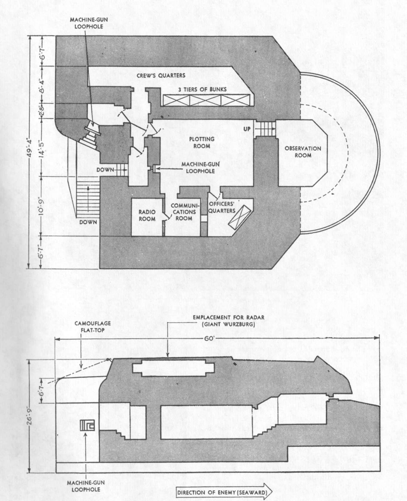
Hyperwar Handbook On German Military Forces Tm E 30 451
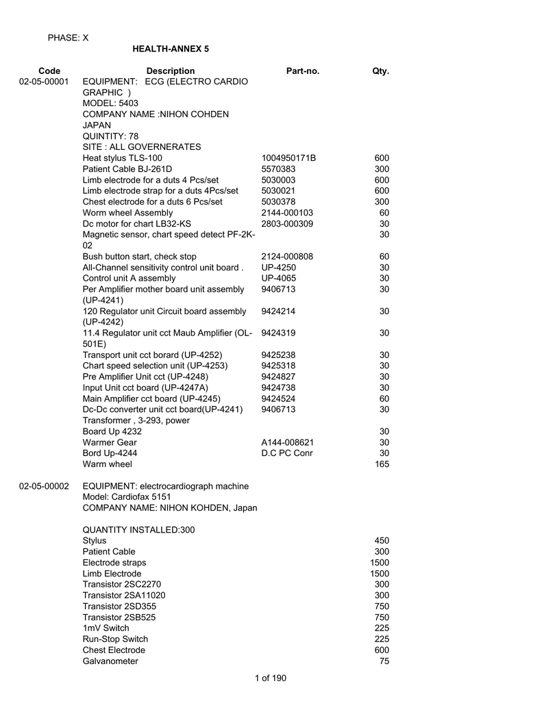
Hkp 15c wiring diagram. 3 phase unit installation 1. Phase no circuit breaker none single phase c single phase kit w 3 three phase circuit breaker hea8ng capacity at 240 volts 5 475 kw 15 1425 to 1500 kw 8 700 kw 20 1900 to 1960 kw 10 950 kw a 1 2 3 45 11. 75c field wire 1. Confirm speed tap selected is appropriate for. Hkp packaged units circuit breaker none single or 3 phase kit. Hkp 15c replaces hkr 15c and hkp 20c replaces hkr 20c in package units.
C us made in the usa by. Buy goodman hkp 15c 15 kilowatt heater coil 51150 btus of heat. Red wires to be on transformer terminal 3 for 240 volts and on terminal 2 for 208 volts 2. Goodman manufacturing company lp. Using the two 1 screws provided mount. Three speed motor wiring select models only see note 3 wh white use min.
When proper operation is ensured replace the control box cover and resume normal operation. Hkp 05c replaces hkr 05c hkp 10c replaces hkr 10c hkp 15c replaces hkr 15c hkp. It is designed specifically to fit inside goodmans packaged heat pumps and air conditioners and features a plug in wiring harness to keep installation quick and simple. See composite wiring diagrams in installation instructions for proper low voltage wiring connections 3. Goodman hkr 15c wiring diagram keyword after analyzing the system lists the list of keywords related and the list of websites with related content in addition you can see which keywords most interested customers on the this website. On the aept mbe airhandler wiring diagram which is included mark an x on the wiring diagram according to the number of heater element rows installed.
The hkp 15c is a 1425 kw heater capable of supplying 48623 btu of heating per hour. When proper operation is ensured replace the control box cover and resume normal operation. Apply the provided wiring diagram for package unit models adjacent to the wiring diagram supplied on the inside of the unit control box cover. Goodman technical support information product brochures and more. Apply the wiring diagram over the one found on the air handlers. Adjacent to the wiring diagram supplied on the inside of the unit control box cover.
Gallery of Hkp 15c Wiring Diagram


%2C445%2C291%2C400%2C400%2Carial%2C12%2C4%2C0%2C0%2C5_SCLZZZZZZZ_.jpg)