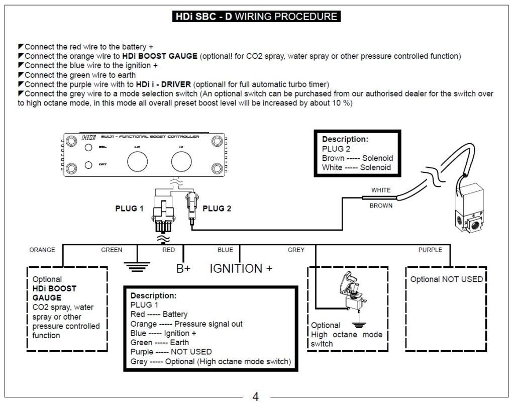
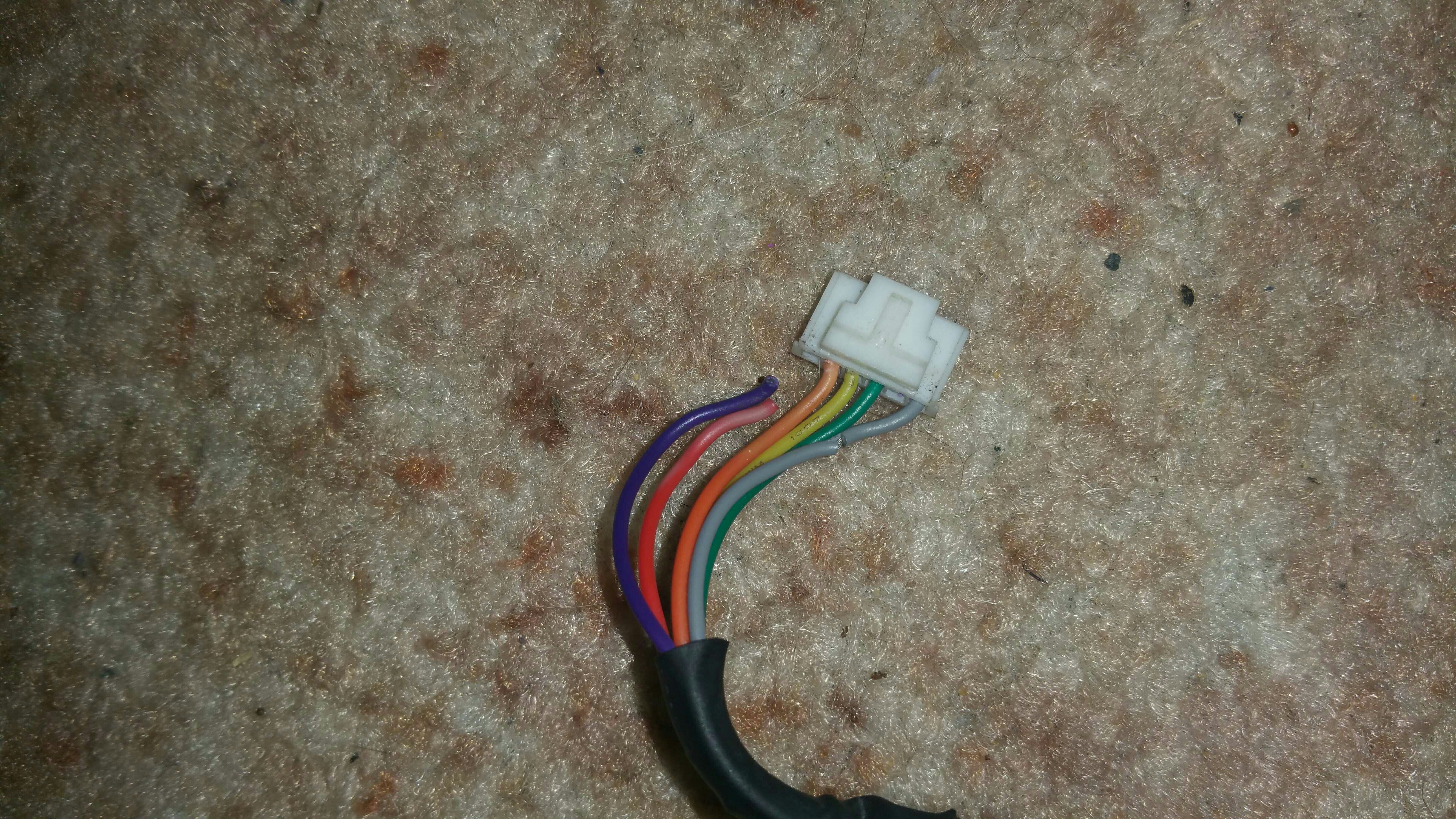
Hdi sbc d rx wiring procedure grey blue red green orange purple plug 1 description. Reduce boost over shoot which most manual boost controller have.
Hdi Boost Controller Issues General Automotive Discussion
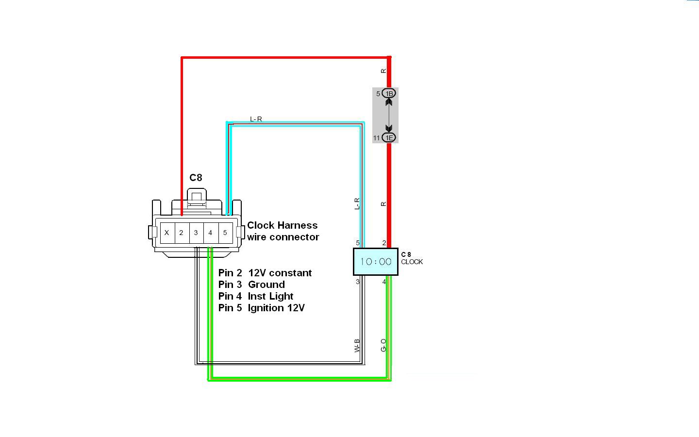
Hdi boost controller wiring diagram. Can someone please help me as im. I have bought a boost controller and have had to rewire things and ive been searching on line for 2 months now on a wiring diagram on positioning of each wire and what it does. Hey guys approaching every one on here again for i for. Just connect the ignition 12v and earth or simply plug in our optional rocket arming switch plug in kit purchase separately and the unit is ready for action. Refer to the following table and diagram for detail on wiring the e boost2. Ive contacted hdi them selves and still no help.
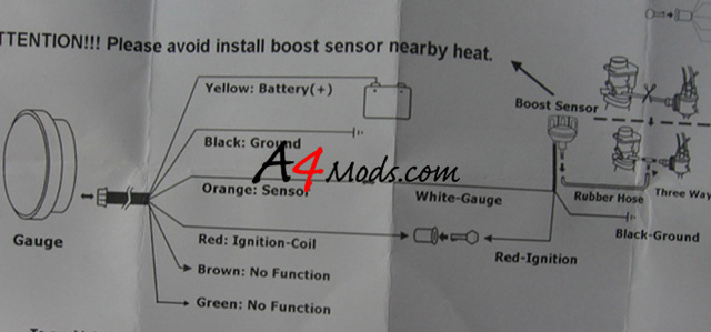
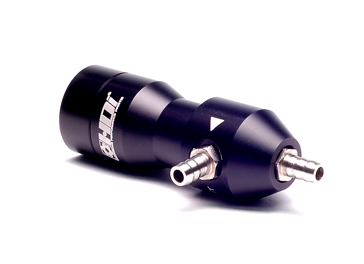
E boost 2 quick start guide wiring. Hdi is proud to release the all new electronic boost controller type r hdi mbc rthe boost controller is specially designed with the effective ceramic ball spring regulator cbsr tm effectively reduced the friction and the reaction time takes in relation to the boost regulation ie. There are three wires out of the six which need wiring up they are green to earth red to battery positive and. Hdi super boost controller type d rx main unit hdi boost adaptor main harness vacuum hose id 4mm od 7mm. Ive been given the wiring diagram and the volour wires arent them same. Electronic boost boost controller type r hdi electronic boost controller type r is specially designed for simple installation easy operation and effective function.
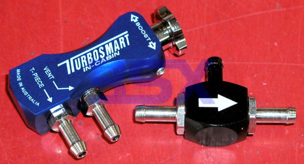
Next is to wire up the hdi sbc d se boost controller wiring loom i have wired mine into my stereo wiring basicially because i can remove this part of the loom and solder all the wires in place outside the car much easier. Once all boost groups are set hold mode in the boost group menu to enter live mode. Once the hdi silicon vacuum hoses are fitted cable tie all fittings with the. Wire connect to red 12 volts switched through ignition. All electrical connections must be soldered. Connecting the t peice and adaptor as per the diagram.
Gallery of Hdi Boost Controller Wiring Diagram