This signal is used for enablingdisabling the driver. In double pulse mode software configurable this signal is counter clock ccw pulse active both at high level and low level.
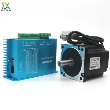
57 Stepper Motor 57bygh76p280 Pg Nema23 Stepper Motor Ratio 3 Level Optional View Stepper Motor Nema 23 Hanpose Product Details From Guangzhou
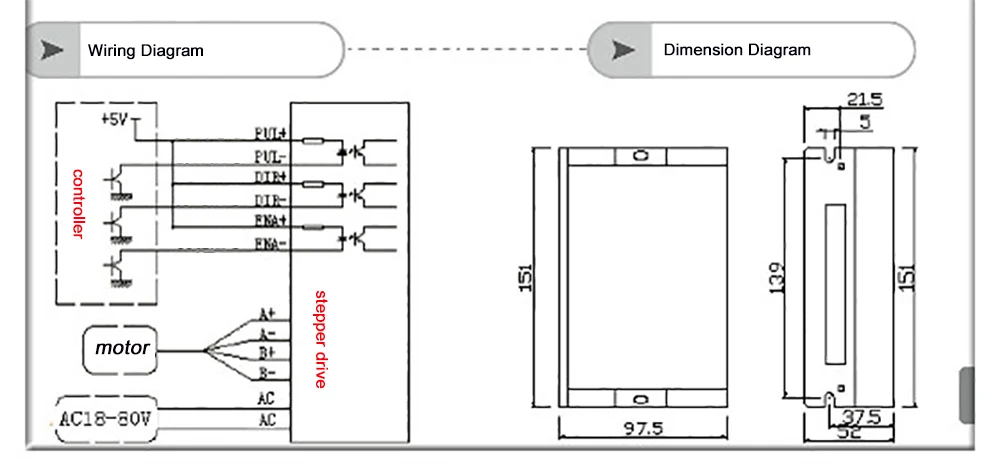
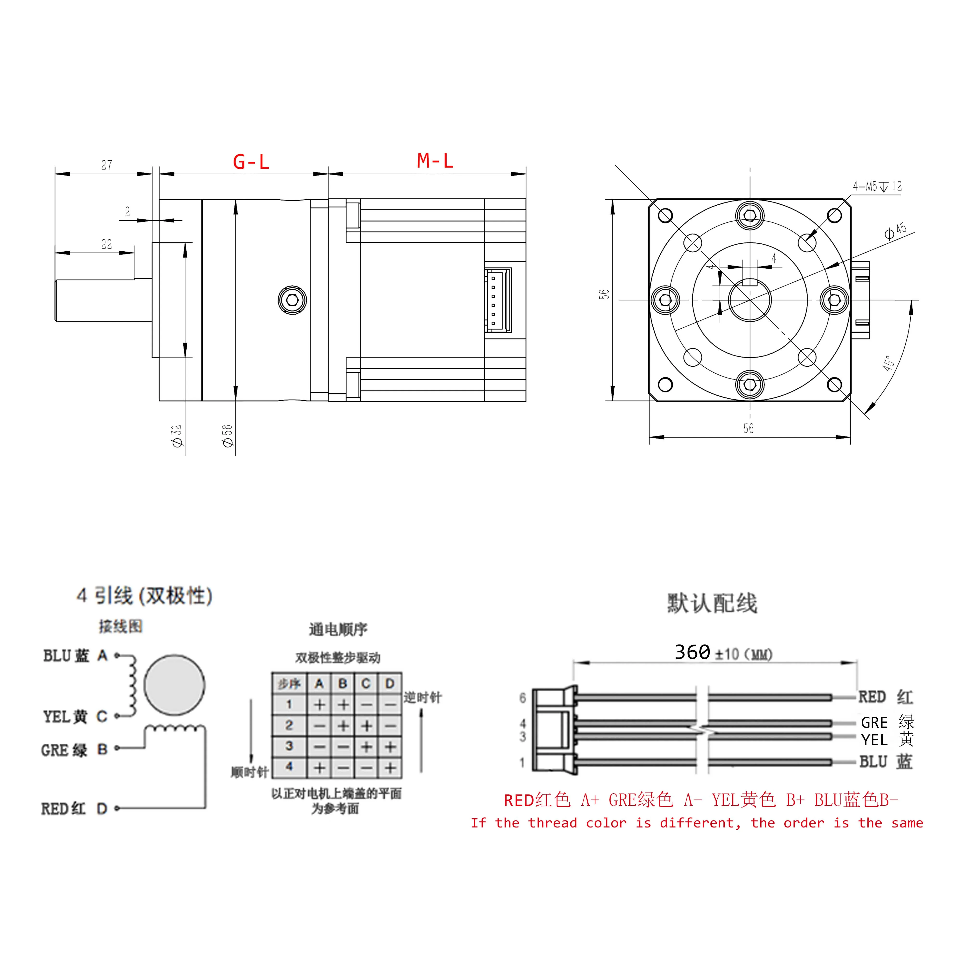
Hbs860h wiring diagram. 4 5v when dir high 0 05v when dir low. 4 dir i 5 ena i enable signal. 54 connections to 232 serial communicationinterface pin1 pin6 pin6 pin1 crystal head definition remark foot transmit data receive data power supply to hisu power ground 55 sequence chart of controlsignals in order to avoid some fault operations and deviations pul dir and ena should abide by some rules shown as following diagram. In default high level npn control. For reliable motion response dir signal should be ahead of pul signal by 5µs at least. Hbs86h leadshine nema34 2phase closed loop motor hybrid servo drive 24 75vac.
The direction signals polarity is software configurable. Atc spindle part 1. Open loop stepper motor driver hbs860h vs. Wiring programming and testing the hitachi wj200 vfd duration. Exchanging the connection of two wires for a coil to the driver will reverse motion direction. Wire inputports a phase ared motor phase a 2 a phase a blue 3 phase bb green motor phase b 4 phase bb black 5 power input ports vcc input power ac24v 70v 6 gnd dc30v 100v input power.
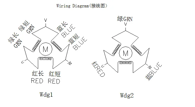
Please note that rotation direction is also related to motor driver wiring match. That rotation direction is also related to motor driver wiring match.
Gallery of Hbs860h Wiring Diagram