A hall effect throttle is simply a magnet and a pickup sensor which works similarly to a potentiometer except rather than turning a manual dial you move a magnet closer to a hall sensor. Im currently doing a hall effect throttle conversion for my kids ride on.

Guide To Hall Sensor Throttle Operation Testing And
Hall effect throttle wiring diagram. Aug 10 2016 173 21 68 uk. For clarity the original effect is sometimes called the ordinary hall effect to distinguish it from other hall effects which have. The hall effect is the production of a voltage difference the hall voltage across an electrical conductor transverse to an electric current in the conductor and to an applied magnetic field perpendicular to the current. Hall effect switch or hall effect sensor switch is a switch that turns on when enough magnetic field near the ic. Aug 11 2016 12 alan quay said. In simple terms when you connect a hall effect throttle to a 5 volt source the sensor will detect the proximity of the magnet to the sensor itself.
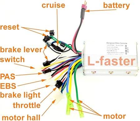
It is connected to all the other electronic parts such as the battery motor and the throttle accelerator display speedometer pas or other speed sensors if exist. You can use hall effect sensor to make many diy projects such as rpm meter magnet. The dn6848 has a built in hall effect sensor schmitt trigger circuit power supply regulator and temperature compensation circuits integrated to a single chip. Standard wuxing throttle with 36v power meter. The electric bike controller is one of the main parts of an electric bike it is the brain of the e bike controlling the motor s speed start stop. Who came back and said this.
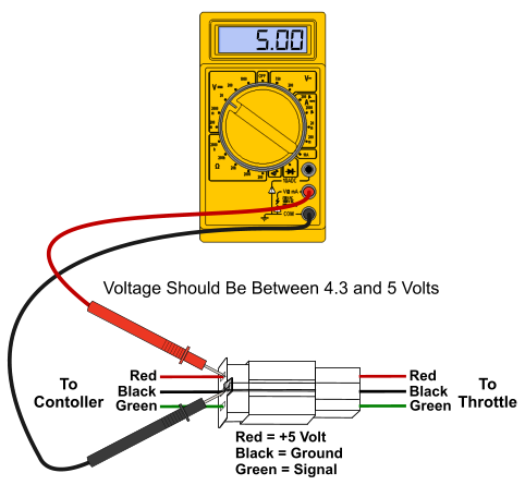
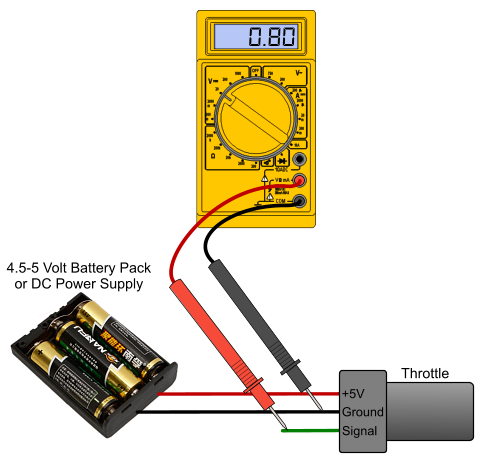
Hall effect sensor ic dn6848 from panasonic is the heart of the circuit. The simplest ebike throttles have three pins in the connector. The circuit diagram shown here is of a hall effect switch. Wiring service bulletin. What is an electric bike controller. The controller sends a 5v power supply to the hand throttle positive along with a second wire that is the ground negativethat leaves the third wire as a signal wire that sends a signal back to the controller to tell it what you want.
I was wondering if anyone has done this before and have also included a brake pedal. If the throttles wire colors are different from the speed controllers wire colors match the wire colors as indicated below. I asked the seller on ebay about wiring up the thumb throttle they said they will pass e mail onto there tech guy. As d8veh says its almost certainly a hall effect device. Controller v1 controller v2 ground. It was discovered by edwin hall in 1879.
If anyone could share their thoughts and possible wiring diagrams on how they connected a hall effect throttle and brake pedal that would be a great help.
Gallery of Hall Effect Throttle Wiring Diagram