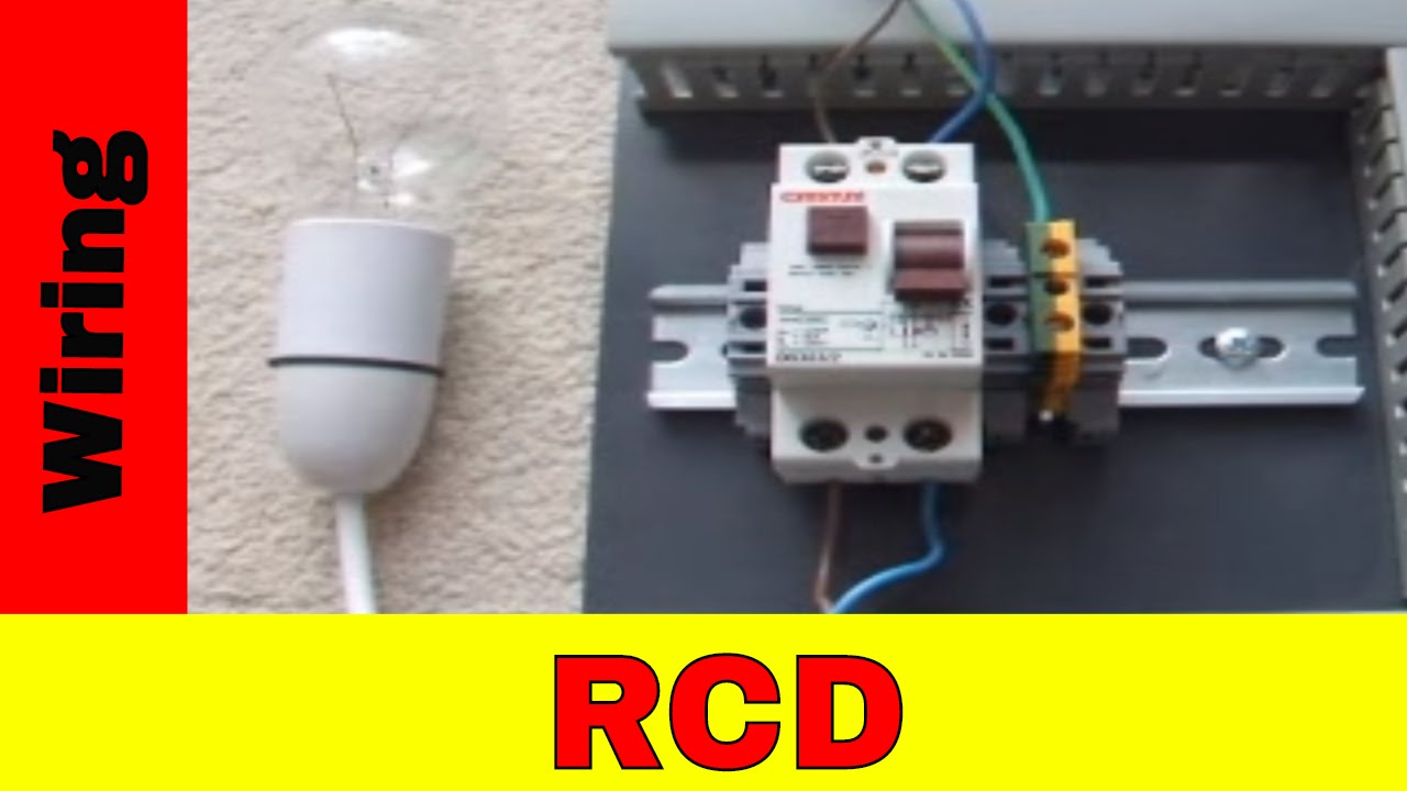
Mounting wiring diagrams diagrams. The unit is made by hager french.

Self Reclosing Rccb Rec3 Installation
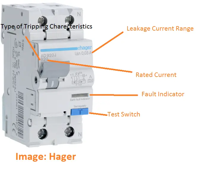
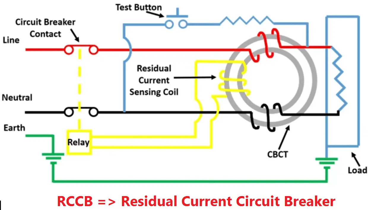
Hager rccb wiring diagram. A second indicator shows that the rccb has been tripped by an earth leakage fault and allows a differentiation between off and tripped status. Thanks for the info john. The over and undervoltage auxiliary is mounted on the left side of the associated hager mcb rccb rcbo. The over and undervoltage auxiliary is mounted on the left side of the associated hager mcb rccb rcbo. I did two a long time ago which have worked fine but just forgotten the details. Hager rccb wiring diagram hager residual circuit breaker rccb elcb 63amp 4 pole 100ma hager rccb wiring diagram wiring diagram is a simplified enjoyable pictorial representation of an electrical circuit.
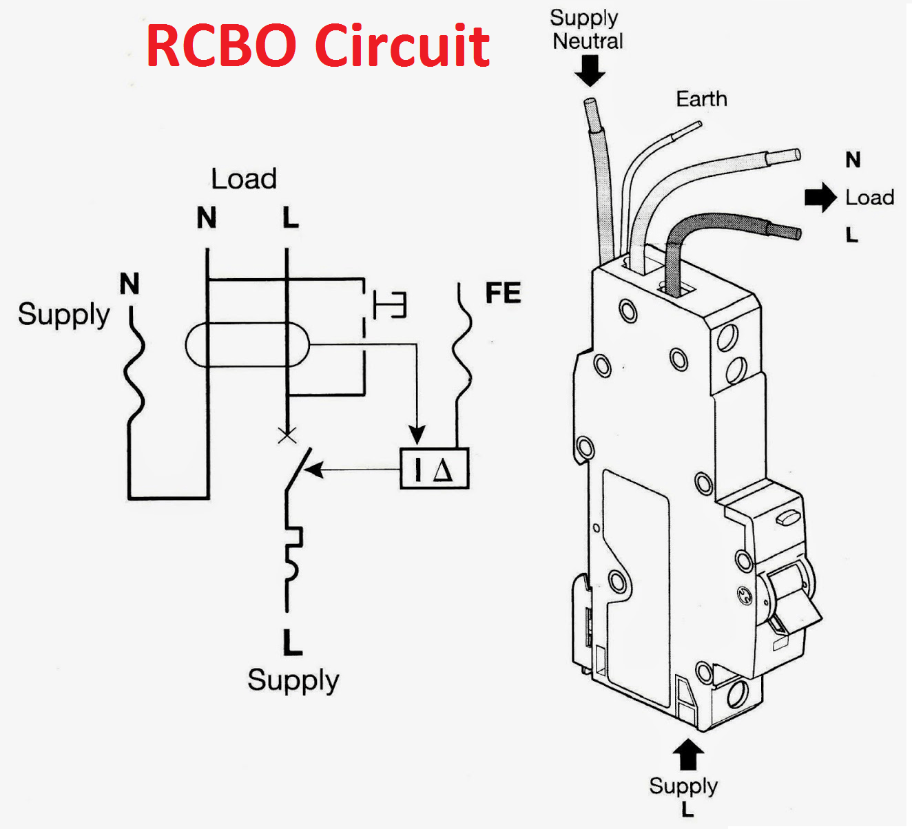
Hagers exclusive survey of electrical professionals carried out by hager shows that many still admit to lacking confidence when it comes to fully understanding the changes. Read more hagers tech manager comments on the new wiring regulations. Hagers residual current circuit breakers range is used to prevent nuisance tripping due to transient overvoltages and in the case of an earth leakage fault. You also have the possibility to install the following accessories. Mounting wiring diagram a second indicator shows that the rccb has been tripped by an earth leakage fault and allows a differentiation between off and. Step by step how to connect up a 10 way wylex dual rcd consumer unit fuse box by luke wichard duration.
The over and undervoltage auxiliary is mounted on the left side of the associated hager mcb rccb rcbo. Cause of a design oversight or subsequent wiring modiication. The over and undervoltage auxiliary is mounted on the left side of the associated hager mcb rccb rcbo. Gsh electrical 179732 views. All hager rccbs incorporate a iltering device preventing the risk of nuisance tripping due to transient voltages lightning line. I am protecting each ring with its own rccb by inserting the rccb between the fuse box and the ring main running 30a wire between the fuse box and rccb of course only a short length.
It shows the components of the circuit as simplified shapes and the capability and signal connections in the midst of the devices. The status of the rccb can be visualised by the colour of the trip.
Gallery of Hager Rccb Wiring Diagram