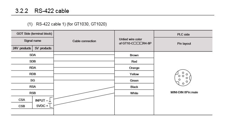
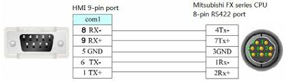
Page 41 reco supported model mmen cable product name model specifications length produ gt01 c10r4 8p for connecting the fxcpu and gt01 c30r4 8p for connecting the fxcpu gt01 c100r4 8p 10 m communication expansion board 37 and got gt01 c200r4 8p 20 m mini din 8 pin d sub 9 gt01 c300r4 8p 30 m pin. Does anybody know where to get this from or had anything to do with programming one etc.

Gt01 C30r4 8p Suitable Mitsubishi F940 930 920 Series Touch
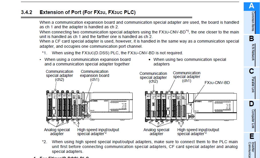
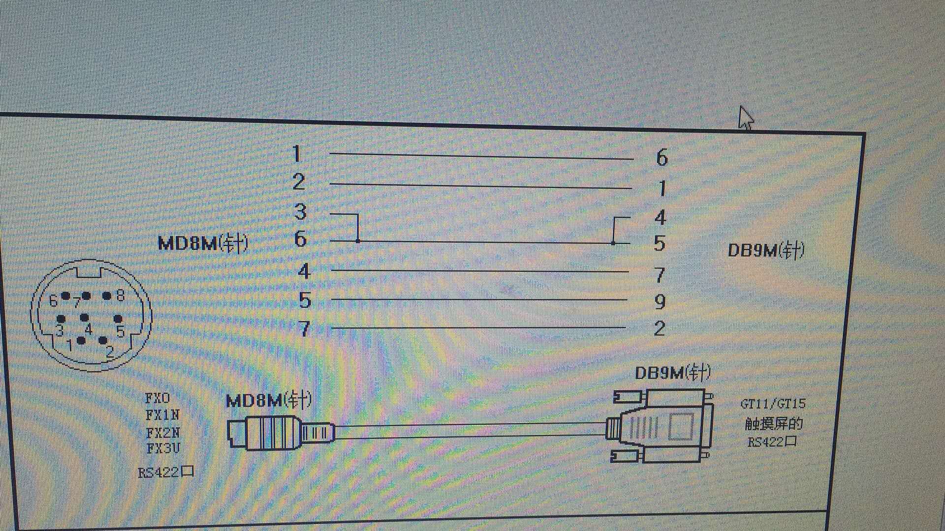
Gt01 c30r4 8p wiring diagram. Draw the io point of the plc and the input output device connection diagram or the corresponding table this part also can be carried out in second steps mitsubishi gt01 c10r4 8p. Hi i have a machine which has an slc504 which is communicating with a telemecanique vsd via a 1746 bas module i have read on the rockwell website that it will have a basic program stored in the module which can be looked at and edited etc via 1747 pbase software. Do not bundle the control and communication cables with main circuit power or other wiring. 1 for connecting the fxcpu and got for connecting the fxcpu communication expansion board and got. Design plc peripheral hardware circuit. Up to 75mm 295inch tdk manual name contents manual number model code got2000 series users manual.
Run the above cables separately from such wiring and keep them a minimum of 100mm 394in apart. 1 for connecting the fxcpu and got for connecting the fxcpu communication expansion board and got mini din 8 pin d sub 9 pin 37. Do not press the got display section with a pointed material as a pen or driver. Not doing so noise can cause a malfunction. Gt01 c30r4 8p gt11h c30r2 6p the cable need to be independently tested by the user to demonstrate emc compatibility when they are used with the got the plc of melsec q series melsec l series melsec qna melsec a series and melsec fx series. Draw the electrical wiring diagram of the other parts of the system.
Gallery of Gt01 C30r4 8p Wiring Diagram