The antenna must be properly installed according to these instructions. Connect the gps 17s port 1 data in data out remote onoff and ground return lines to your nmea device or pc.

Kia Car Radio Stereo Audio Wiring Diagram Autoradio Connector
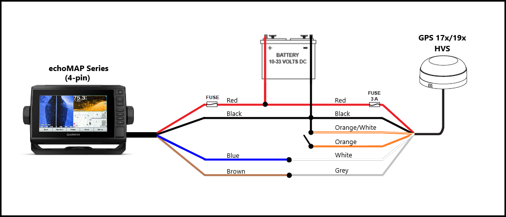
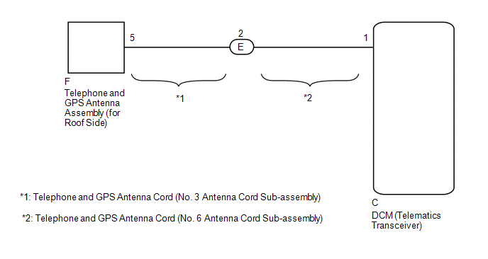
Gps antenna wiring diagram. Use the following diagram to connect the gps 17n17hvs antenna to a red and black wires shielded twisted pair wiring for extended runs of wire. The gps 19x nmea 0183 hvs can be connected to a garmin chartplotter or another nmea 0183 compliant device. The garmin gps 19x nmea 0183 hvs high sensitivity gps antenna provides position information over nmea 0183. Antenna height h a b q. Gps instructions for use with customers antenna installation. The antenna height can then be computed from the equation.
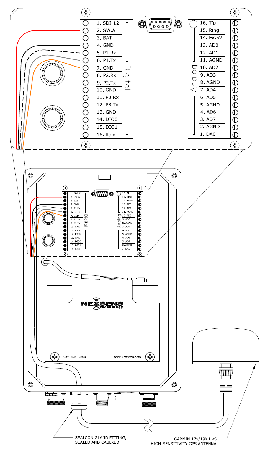
Garmin 17x19x hvs gps high sensitivity antenna nexsens with regard to garmin gps antenna wiring diagram image size 448 x 375 px and to view image details please click the image. Improper installation could damage the instrument and void the warranty. The gps antenna is to be affixed by silicone or 2 sided tape and should be removable in case battery goes dead. The basic installation requires the black white and red wires to be connected to the unit. Port 2 is used for rtcm input only. Install gps speedo as shown on back.
Locate the wiring harness and look at the color coded wires on the non plug end. After mounting the gps 17 in the desired location connect the wiring. For reliable communication it is essential that the gps 17 and the receiving device share the same ground. Here is a picture gallery about garmin gps antenna wiring diagram complete with the description of the image please find the image you need. The remaining wires are not used except that in specialized digital input scenarios and should be clipped off or taped up if not being used. Leica antennas use a measuring hook to determine the vertical distance between the mark and.
All wiring connections must be shielded from water spray. Garmin hereby grants permission to download a single copy of this manual onto. Ensure that the antenna mates securely with the tripod head and that any gap b between the tripod head and arp is measured and included.
Gallery of Gps Antenna Wiring Diagram