Blink codes if a display unit is. Garmin spread spectrum with chirp technology used on the gsd 26 not only gives better target separation and resolution at.
The Marine Installer S Rant Installing The Garmin Gsd 24
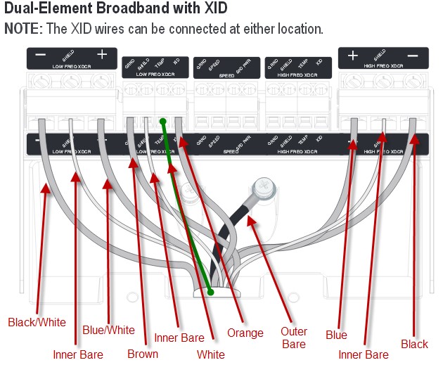
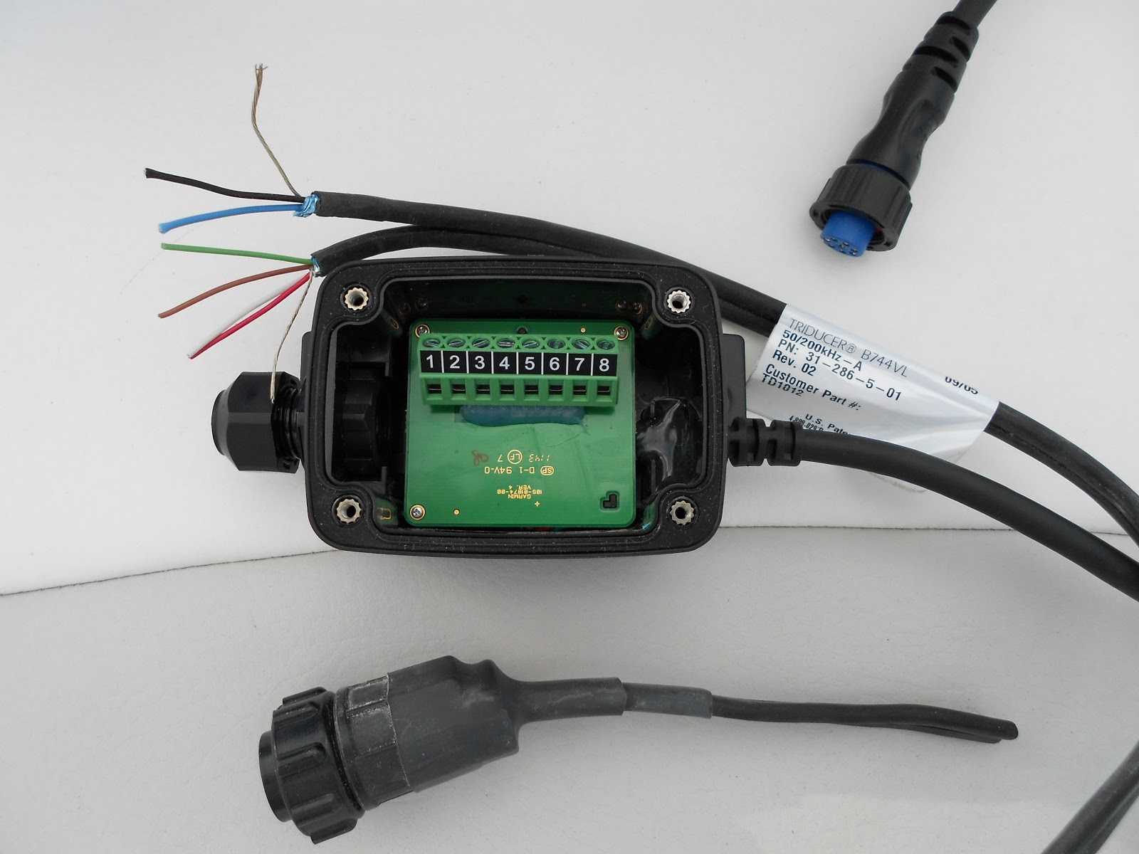
Garmin gsd 22 wiring diagram. Refer to the marine network wiring diagrams on page 4 for connecting the gsd 22 to compatible garmin. Transducer for the gsd 22. Transducer cable extensions are available through your garmin dealer. Refer to the marine network wiring diagrams on page 4 for connecting the gsd 22 to compatible garmin devices. Gsd 22 wiring connection and marine network wiring and cables. Wiring diagrams for conventional non chirp transducers.
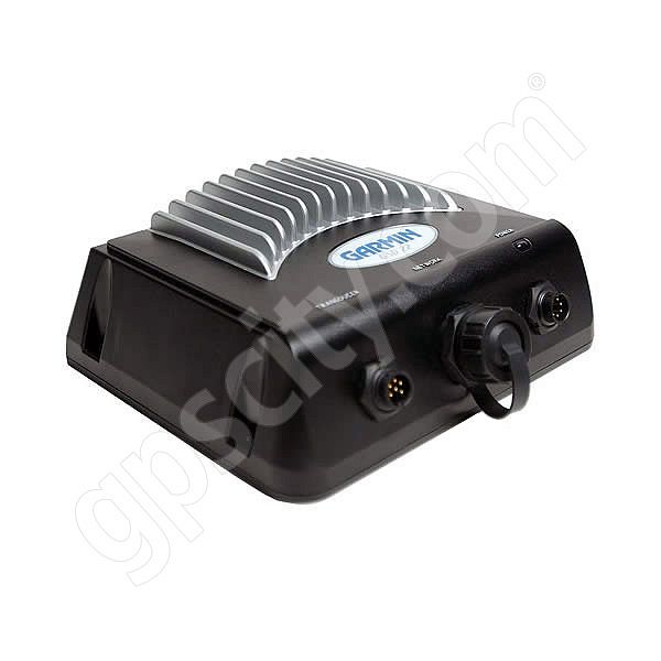
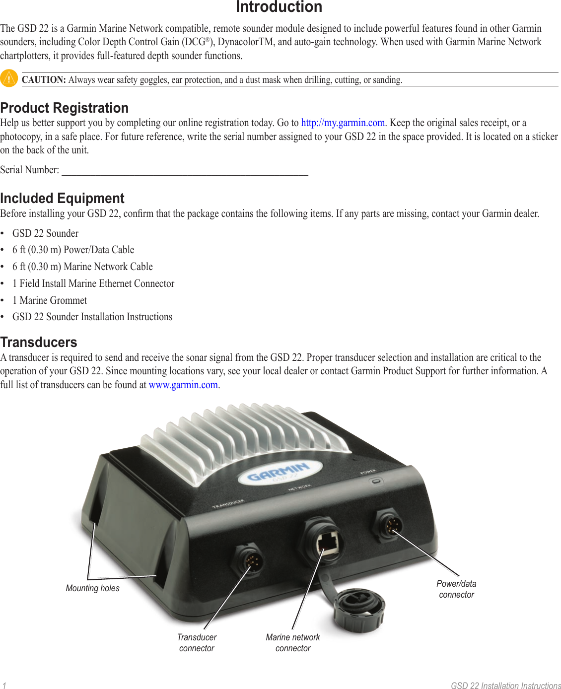
After installing the gsd 22 module connect the powerdata and transducer cables to the appropriate receptacle. Check to see if an adapter cable exists see the adapters page. This black box sounder connects to your chartplotter over the garmin marine network to provide high speed data returns and super crisp detail. Refer to the following canet or marine network wiring diagrams for connecting the gsd 22 to compatible garmin units. Marine equipment garmin gsd installation instructions manual. Garmin gsd 26 installation instructions manual.
Airmar p79 adjustable in hull 010 10327 00 50200 600w 4512 800 1200. You also can use the gsd 22 with garmins canet to connect to non network chartplotters. Sounder module 12 pages insert the o ring into the end of the connector. Automotive oem solutions blog careers garmin express rv oem solutions shop all sales rv 890 rv navigator with a large edge to edge 8 display preloaded campgrounds and custom routing for the size and weight of your rv or towable trailer. Before attempting to rewire a transducer connector you should. You can extend the wiring of the gsd 20 powerdata cable up to 100 30 m total length.
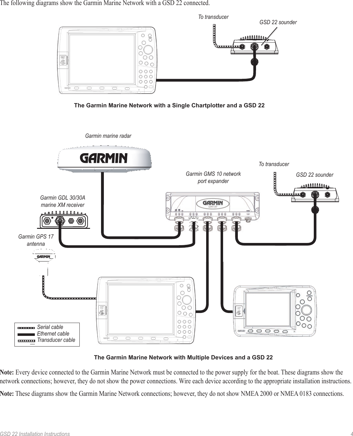
Transducer wiring diagrams you can use these diagrams to. The garmin marine network with a single mfd and a gsd 22 garmin marine radar garmin gdl 3030a marine weatheraudio satellite receiver gps 17 the garmin marine network with multiple units and a gsd 22. These diagrams are for the use of professional installers. Once connected any plotter on the network can view the 22s detailed sonar data and overlay it on the map page. Refer to the following wiring diagrams for connecting the gsd 20 to compatible garmin units. Use 22 awg 4 conductor shielded cable for data cable and 18 awg for power.
Refer to the following sections. Connect the powerdata and transducer cables to the connectors on the back of the gsd 22. Page 7 the following diagrams shows the garmin marine network with a gsd 22 sounder module connected.
Gallery of Garmin Gsd 22 Wiring Diagram