These wires are used only for garmin data sharing between the striker and the echomap 2 series devices. To flush mount the gpsmap cc 1.
Gpsmap 276c 296 Mini 9 Pin Bare Wire Power Data Audio Cable
Garmin gps wiring diagram. Garmin 3210 wiring diagram. In europe contact garmin europe ltd. Gps connector or cable wiring scheme. Pinouts gps receivers connectors garmin pinouts. For macintosh users garmin does not support macintosh at this time and does not have macintosh software or connectors available. Red and black the red wire will connect to your positive battery terminal and the black wire will connect to your negative battery terminal.
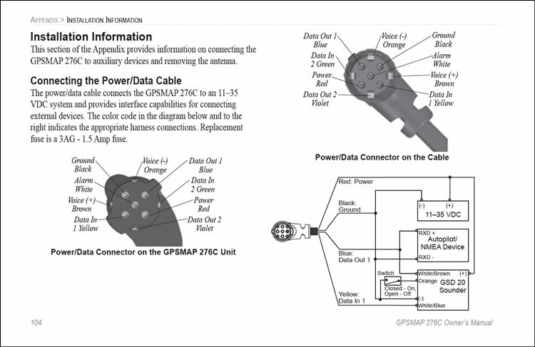
Pinout of garmin gpsmap power and data cableused by gpsmap 276c gpsmap 278 gpsmap 296 gpsmap 376c gpsmap 378 gpsmap 396 gpsmap 478 gpsmap 495 gpsmap 496. Pinouts devices connectors. Information for wiring a garmin gps to a din 8 connector is provided as a courtesy to macintosh users. Use the following diagram to connect the gps 17n17hvs antenna to a red and black wires shielded twisted pair wiring for extended runs of wire. Connecting the device to a remote gps antenna. Contact garmin product support by phone.
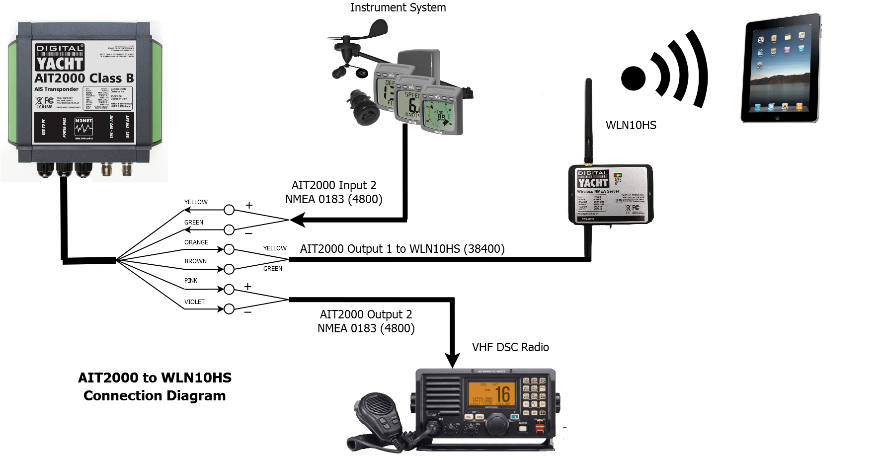
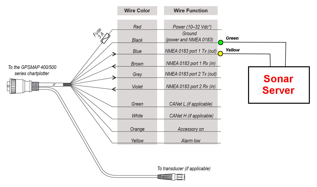
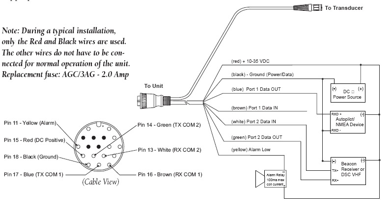
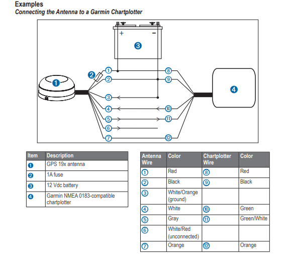
Blue and brown1 optional the blue wire is the tx transmit and brown is the rx receive wire. 9133978200 or 8008001020 mondayfriday 8 am5 pm central time. Item description 12 vdc power source wiring harness nmea 0183 compliant device item garmin wire function garmin wire color nmea 0183 device wire function power red power ground black. If you should encounter any difficulty while using your gps 17 or if you have any questions in the usa. Next are the wiring diagram examples showing the gpsmap cc using the pin. See the following wiring diagram for a sample of how to accomplish this.
Garmin gpsmap power and data cable pinout. Nmea 0183 connection diagram. The striker powerdata cable consists of four wires. Loading the new software on a memory card. Garmin hereby grants permission to download a single copy of this manual onto.
Gallery of Garmin Gps Wiring Diagram