The original version has a 5 s delay. It shows the components of the circuit as simplified shapes and the capability and signal friends amid the devices.
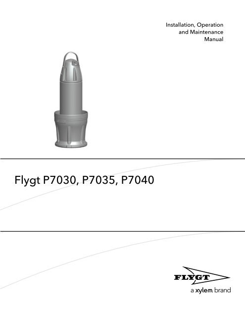
Flygt P7030 P7035 P7040
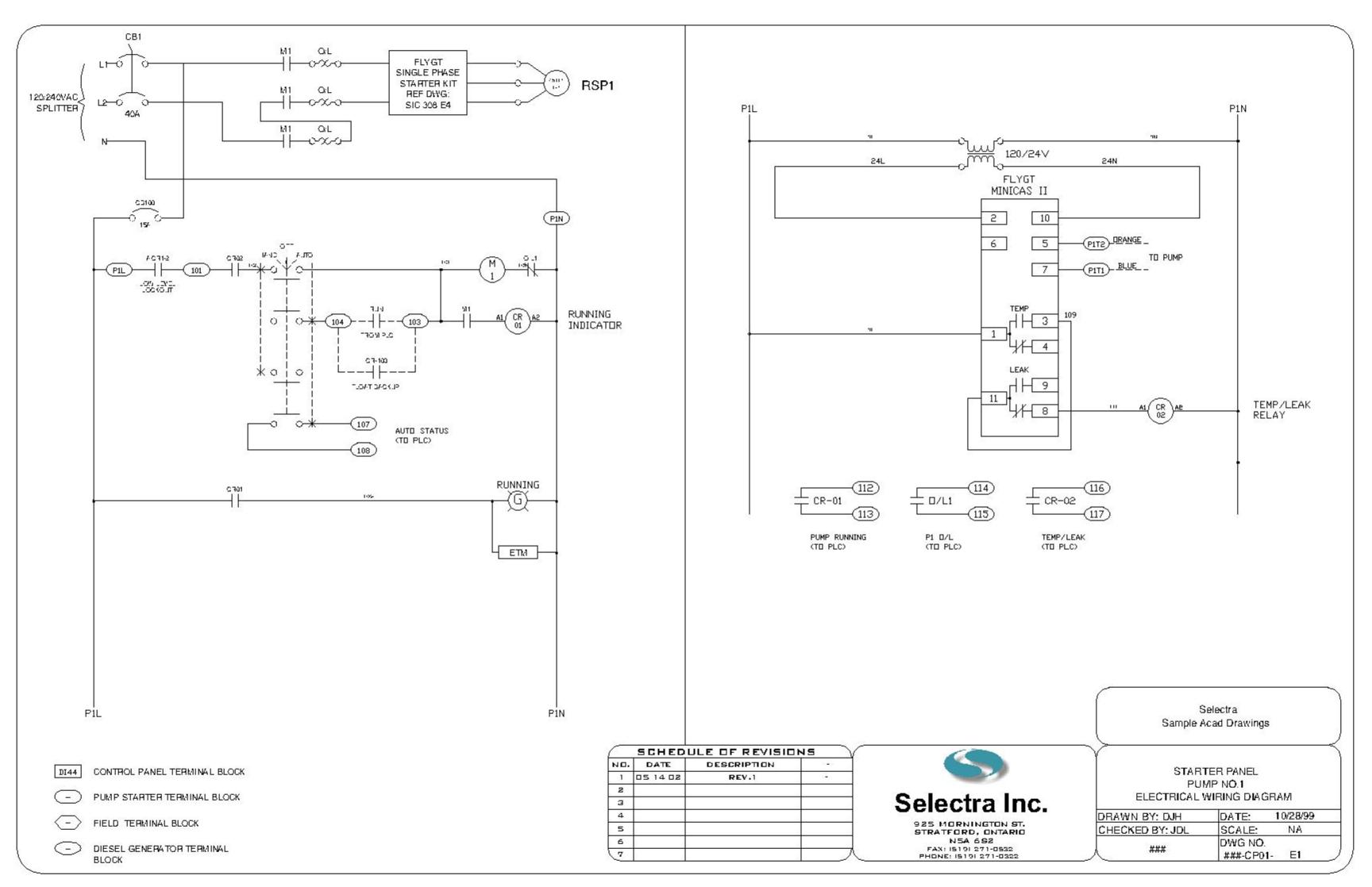
Flygt minicas wiring diagram. This version also has an. The circuit diagram on the side of the unit. It is designed for the 3000 series pumps up to model 3301 and for the mixer program. Itt flygt minicas ii is a supervision relay for tempera ture and leakage sensors. Cls for water in oil detection. It provides protection for the most common threats against a submersible pump.
Minicas ii requires resetting after overtemperature fault. Description terminal description number go relay pump interlock 5a250v ac. Please see technical data. Go relay pump interlock 5a250v ac. Terminal this table describes the terminals for the relay outputs. 2 reset leakage 10 s 8 11 9 high temp 4 13 6 2 power supply 24 v acdc 120 v ac and 230 v ac 12 vdc 7 5 minicasii sensor.
High temperature and leakage. Minicas ii is a monitoring relay used primarily with small and medium pumps and mixers. Wiring diagram minicas llfus 120 mode of operation. If pump shutdown is desired for a leakage situation connect minicas contacts 1 3 11 8 in series. Every component is designed and manufactured to deliver sustained high efficiency. In case of alarm the pump is stopped or an alert is given by means of lamps and relays.
Flygt n pumps take on the toughest applications and get the job done. A number of condition monitoring sensors are available for the itt flygt pump range. Thanks to patented n technology with its innovative self cleaning impeller flygt n pumps deliver the highest total efficiency. Flygt minicas wiring diagram wiring diagram is a simplified suitable pictorial representation of an electrical circuit. 1 3 closed 1 4 open. Dc power supply required for 24 vdc.
Overtemperåture indication note leakage indica tion. Wiring diagram minicas llfus 120. Installation wiring relay outputs wiring relay outputs illustration this is an illustration of section 6 of the base unit terminal block. Unit operates on 24 vac 24 vdc or 120 vac supply. Check the delay of the leakage alarm. Leakage relay contacts.
The updated version has a 10 s delay. Overtemperature relay contacts. Thermal switches for stator overtemperature. They lower your energy bill and reduce unplanned maintenance costs. Wiring diagram minicas fus us version wiring diagram minicasfus see note 2 notes. 11 8 closed 11 9 open.
Wiring diagram minicas fus us version pump housing thswitch lk. Amber led indicates supply on. 24 vac24 voc 120 vac 2. There is not a separate indication when two leakage sensors are used. In normal conditions when the minicas 120 is powered the green led is on and the relay contact status is as follows. Control transformer required only for 24 vac applications.
Wiring diagram minicasfus control transformer fl minicas 12 10 ac neutral see cc yel blu vdc orn starter in terlocking circuit 120 vac rgnd notes. Minicas ii resets automatically after leakage fault. The sensors are monitored by the itt flygt minicas ii supervision relay which is situated in the panel.
Gallery of Flygt Minicas Wiring Diagram