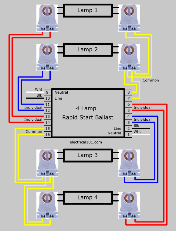
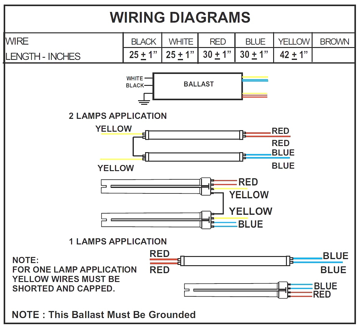
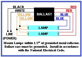
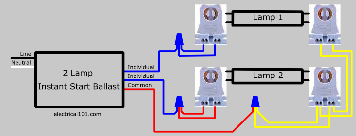
Assortment of fluorescent ballast wiring diagram. Parallel ballasts can only be wired in parallel according to the diagram on the ballast.

How To Wire Electronic Ballast
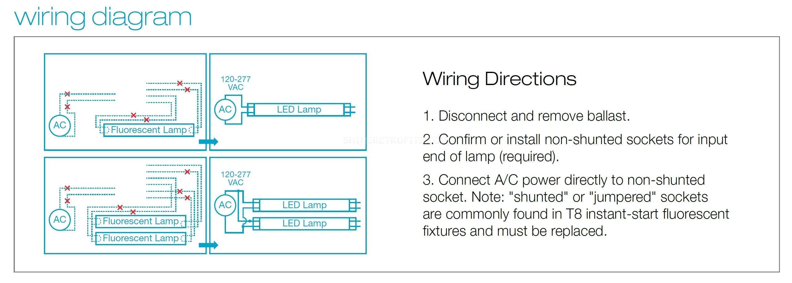
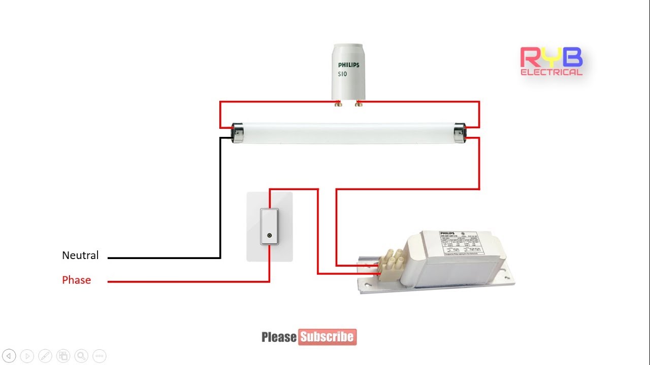
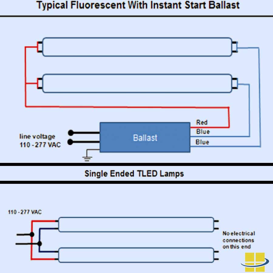
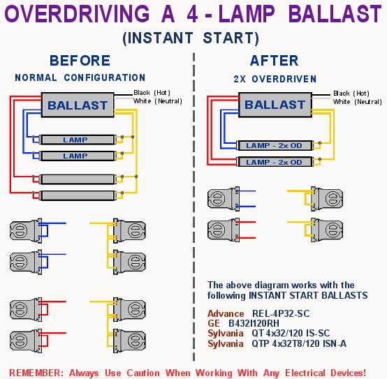
Fluorescent ballast wiring diagram. A wiring diagram is a streamlined standard pictorial representation of an electric circuit. Variety of fluorescent ballast wiring schematic. It reveals the elements of the circuit as streamlined shapes and the power and also signal links in between the devices. Changing the wiring on a fluorescent light fixture from series to parallel involves changing the ballast from a series to a compatible parallel ballast. There is no preheating of the electrodes for the highest energy efficiency but are best suited for a limited amount of switching 10000 to 15000 switch cycles before failure. There are four basic types of fluorescent ballasts.
It reveals the components of the circuit as streamlined forms and the power and also signal links in between the gadgets. Fluorescent ballast wiring schematic. Commercial cfls use a separate ballast. August 16 2018 by larry a. In concept replacing a fluorescent lamp ballast or transformer is pretty simple. A wiring diagram is a streamlined standard pictorial representation of an electrical circuit.
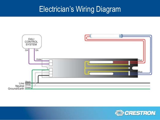
Ballasts have a wiring diagram to show how they connect to the lampholders. Fulhams easy to use wiring diagram finder for workhorse wham and longhorse electronic fluorescent ballasts. Ballast manufacturers like phillips offer technical support including a telephone number to call for assistance. Series ballasts can only be wired in series according to the diagram on the ballast. Instant start electronic ballasts use a high starting voltage about 600 volts to start very quickly less than 01 seconds. What can be intimidating is the plethora of wiring diagrams on the new ballast none of which matches exactly the wiring diagram on the original unit.
Gallery of Fluorescent Ballast Wiring Diagram