See notes below 3. For patch cables 568 b wiring is by far the most common method.
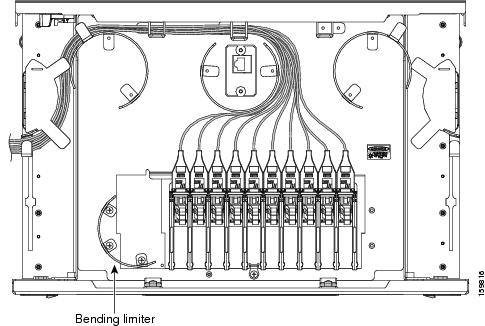
Cisco Ons 15454 Dwdm Network Configuration Guide Release 10
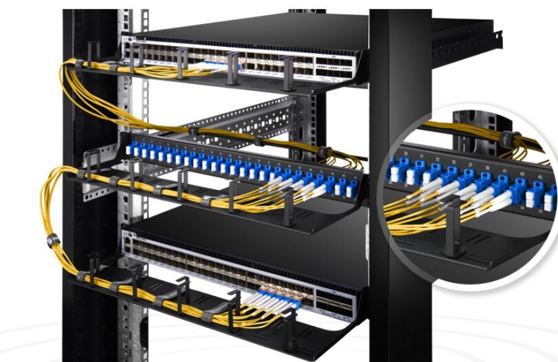
Fiber optic patch panel wiring diagram. Fiber optic patch panel is the wiring distribution equipment of the user terminal in the optical fiber system which can realize the functions of fiber fusion distribution and scheduling. Fiber optic patch panels. Fiber optic cable is less common in residential applications than coax and cat 5e but it holds tremendous potential for delivering massive amounts of data video and audio at very high speeds. How to connect patch panel to switch why a 24 port patch panel is needed for a 24 port switch. In addition the patch panels are specially designed with a working tray with the capability. It shows the components of the circuit as simplified shapes and the capability and signal associates along with the devices.
For a structured media setup you can buy bundles of wiring with two runs each of cat 5e and coaxial cables. It can also be used as a separate node for long distance fiber transmission. Some people may ask that is it necessary to use a patch panel or is it possible to replace the 24 port patch panel by a 24 port gigabit switch. A basic fiber optic panel is typically a metal enclosure that encloses the adapter panels and fiber splice trays. Either wiring should work fine on any system. The importance of selecting the right fiber optic media is closely followed by the importance.
See the page 12 for a summary of part number information covering fiber conn fiber optic patch cables. Notes for wiring diagrams above. The fiber optic patch panels come complete with the adapters required and simple splice management kit. Unloaded or pre loaded we have a number of different customizable options available to fit whatever application you require. There is no difference in connectivity between 568b and 568a cables. Patch your fiber optic cables to your enclosures with these convenient patch panels and adapters.
They make it easy to terminate fiber optic cables and provide access to the cables individual fibers for cross connection. Patch panel to switch diagram. For a straight through cable wire both ends identical. Fiber optic patch panels are also known as fiber distribution panels. Actually it is better to use a 24 port patch panel to a 24 port. 12 fiber 24 core 48 72 and 144 fiber configurations.
A complete line of fiber optic patch panels and termination kits. These adapter panels and optical cassettes are supported within the rack mount and wall mount enclosures. Fiber optic patch panel wiring diagram wiring diagram is a simplified agreeable pictorial representation of an electrical circuit. Standard 1u 2u 3u and 4u liu fiber optic patch panels and optical distribution frames odf.
Gallery of Fiber Optic Patch Panel Wiring Diagram