Page 5 wiring diagrams this page. 7 string wiring humbucker bridgedp701 middledp710 reverse neck ibz 5 way switch 1 volume 1 tone.

Tech Info Oemfancontrol
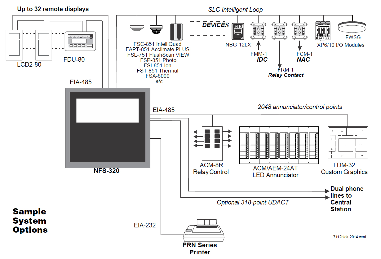
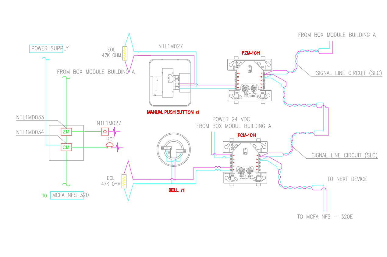
Fcm 1 wiring diagram. It shows the components of the circuit as simplified shapes and the gift and signal contacts amongst the devices. See wiring diagram fig. The fcm 1 has two pairs of output termination points available for fault tolerant wiring and a panel controlled led indicator. Wellborn variety of notifier fcm 1 wiring diagram. A wiring diagram is a simplified conventional pictorial representation of an electric circuit. This module can be used to replace a cmx 2 mod ule that has been configured for supervised wiring operation.
Maximum slc current draw. All wiring shown is supervised and power limited. Fcm 1 rel wiring diagram wiring diagram is a simplified customary pictorial representation of an electrical circuit. Releasing control module smb500. 32f to 120f 0c to 49c dimensions. Addressability al lows the fcm to be activated either manually or through panel programming on a select zone or area of coverage basis.
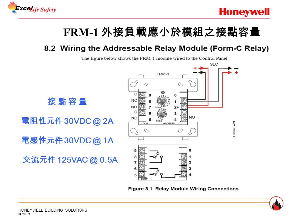
4675 h x 4275 w x 14 d mounts to a 4 square by 218 deep box specifications for frm 1. Install contact closure devices per manufacturers installation instructions. 15 to 32 vdc. It reveals the parts of the circuit as streamlined forms and the power as well as signal links in between the tools. Fcm 1 control module the fcm 1 addressable control module provides notifier intelligent control pan els a circuit for notification appliances horns strobes speak ers etc or to monitor a telephone circuit. Neck neck middle middle bridge split middle bridge.
July 18 2018 by larry a. 65 ma led on temperature range. 5 for frm 1 general. Compatibility requirements to ensure proper operation this module shall be connected to a. Maximum slc current draw. Any number of ul listed contact closure devices may be used.
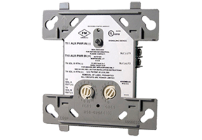
15 to 32 vdc. Control module barrier required by ul for sepa rating power limited and non power limited wiring in the same junction box as fcm 1 rel. The fcm 1 has two pairs of output termination points available for fault tolerant wiring and a panel controlled led indicator. Control module barrier required by ul for sepa rating power limited and non power limited wiring in the same junction box as fcm 1 rel. This module can be used to replace a cmx 2 module that has been configured for supervised wiring operation151. Fmm 1 connect modules to listed compatible notifier control panels only.
Gallery of Fcm 1 Wiring Diagram