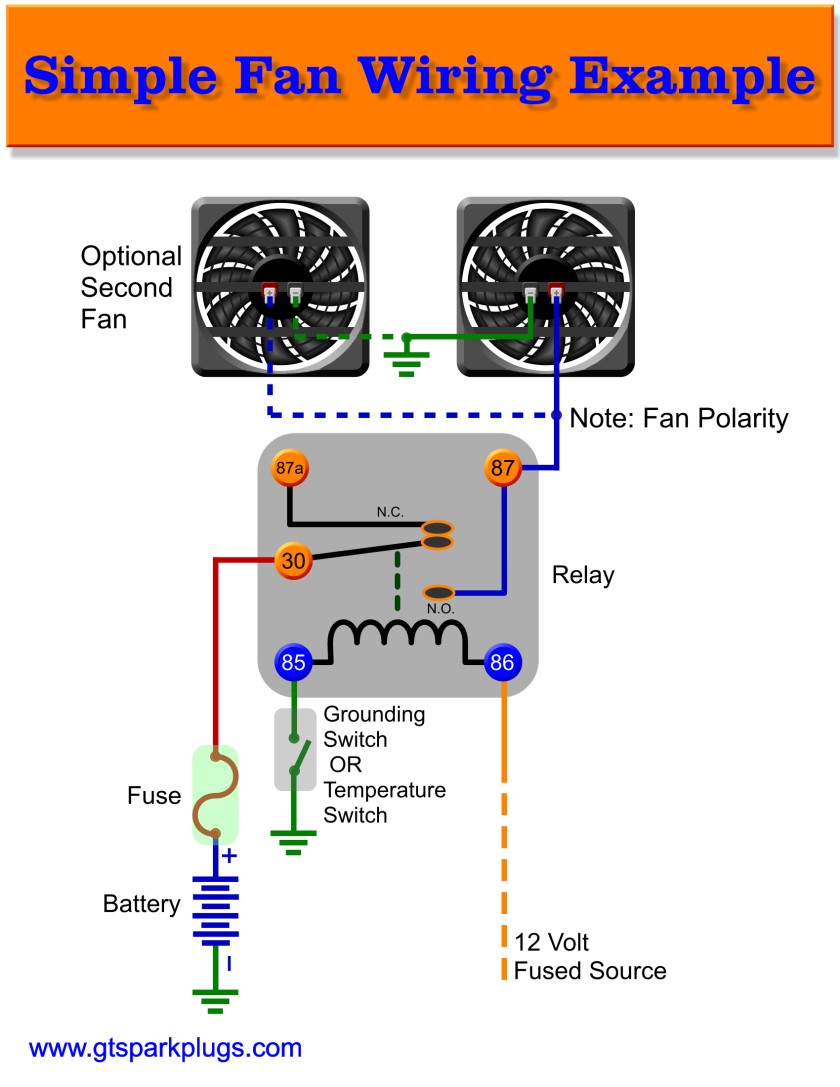
A wiring diagram is a straightforward visual representation from the physical connections and physical layout of your electrical system or circuit. Load voltage to the fan is wired at the upper left push in terminal.

Ss 8226 Damper Fan Circuit Diagram Download Diagram
Fan control center wiring diagram. A wiring diagram is a type of schematic which makes use of abstract photographic signs to show all the interconnections of components in a system. Symbols that stand for the parts in the circuit and lines that represent the links between them. A wiring diagram is a simplified standard photographic depiction of an electrical circuit. Variety of hvac fan relay wiring diagram. As honeywells illustration shows the two fan terminals are on the upper and lower left side of the control. This is a video lesson on wiring a fan control centerplease feel free to comment and rate this video.
Fan control center wiring diagram. It shows how the electrical wires are interconnected and can also show where fixtures and components might be coupled to the system. Electrical wiring representations are made up of 2 points. Line voltage is wired at the bottom left push in terminal. Wellborn collection of fan control center wiring diagram. A wiring diagram is a streamlined standard photographic depiction of an electric circuit.
It reveals the parts of the circuit as streamlined shapes and the power as well as signal connections between the devices. It reveals the components of the circuit as simplified forms as well as the power and signal connections in between the devices. Fan control center wiring diagram what is a wiring diagram. December 18 2018 by larry a.
Gallery of Fan Control Center Wiring Diagram