With the photo eye removed from the circuit and if you have a ohm meter you can test the ohms thru the black and red wire coming out of the photoeye. This photocell is used to control outdoor flood lights on the exterior of a.

Power Turbine Control System N2 Wiring Diagram Continued
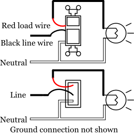
Electric eye wiring diagram. We show you where to attach the red wire the black wire and the grounds. Wiring a photo cell is explained in the video. Connect the black wire hot line to the black wire of the photocontrol. To connect a photoelectric switch to a light for example begin by connecting all three of the white cables white neutral cable from house supply white cable on light white cable on photoelectric switch and tying them together with a wire nut. Connect the white wire from the light fixture and the white. Connect the black wire of the light fixture to the red wire of the photocontrol.
Wire the photoelectric switch. To generate a waveform analogous to an eye diagram we can apply infinite persistence to various analog signals a well as to quasi digital signals such as square wave and pulse as synthesized by an arbitrary frequency generator afg. For 120 volt units. When you shine light in the face of the photo eye you should see a increase in resistance and when you cover up the photo eye the resistance should drop to close to zero allowing current to pass. Jan 10 2020 16 garage door electric eye wiring diagramchamberlain garage door opener sensor wiring diagram craftsman garage door opener sensor wiring diagram garage door opener sensor wiring diagram garage door sensor wiring diagram genie garage door opener sensor wiring diagram liftmaster garage door opener sensor wiring di. An eye diagram is used in electrical engineering to get a good idea of signal quality in the digital domain.
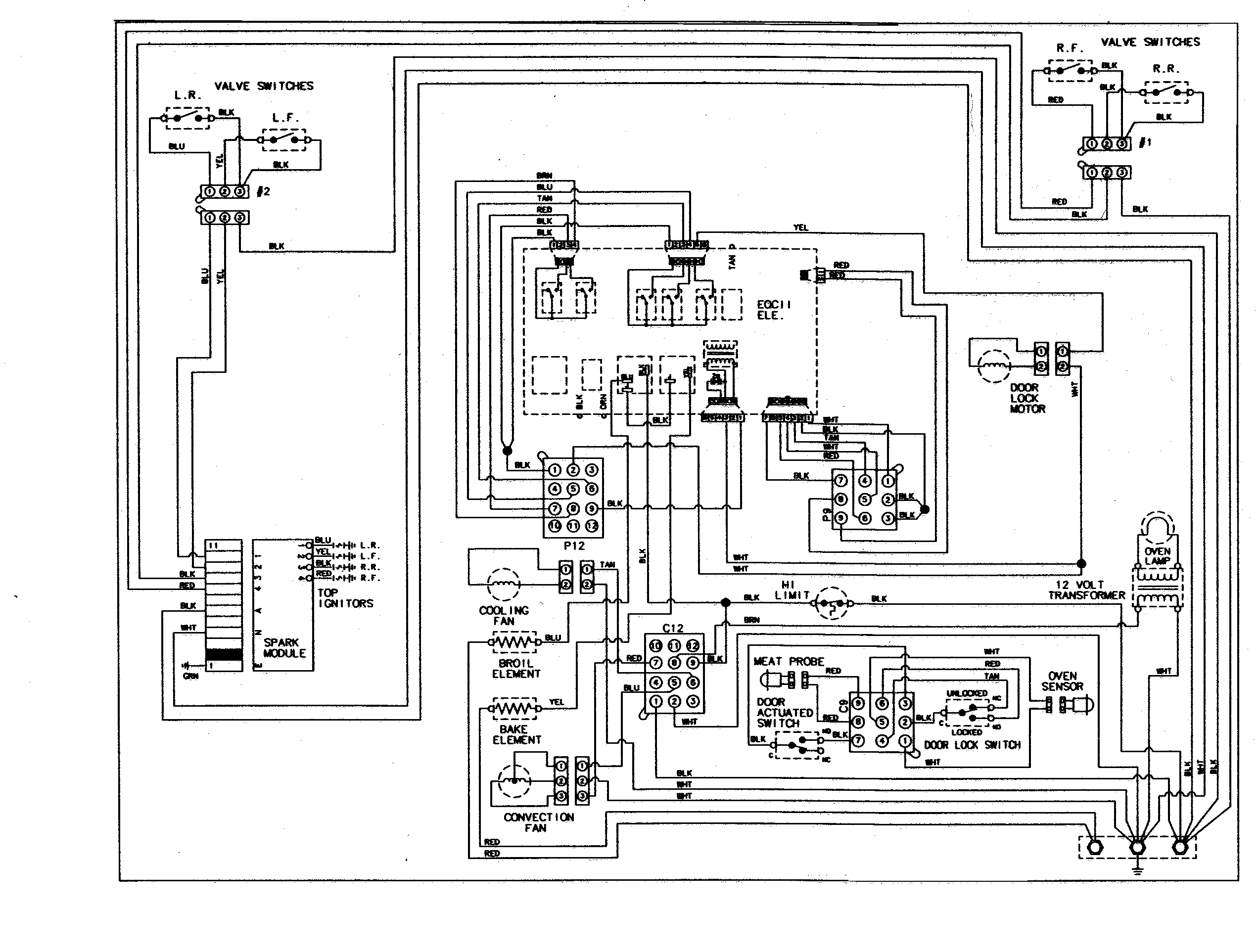
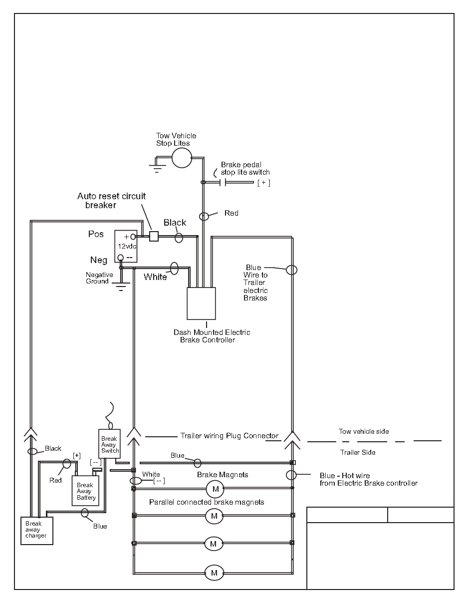
Refer to the wiring diagrams below and choose the appropriate diagram.
Gallery of Electric Eye Wiring Diagram